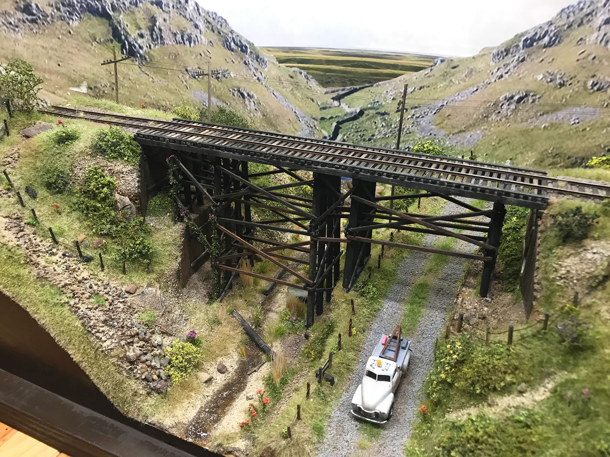
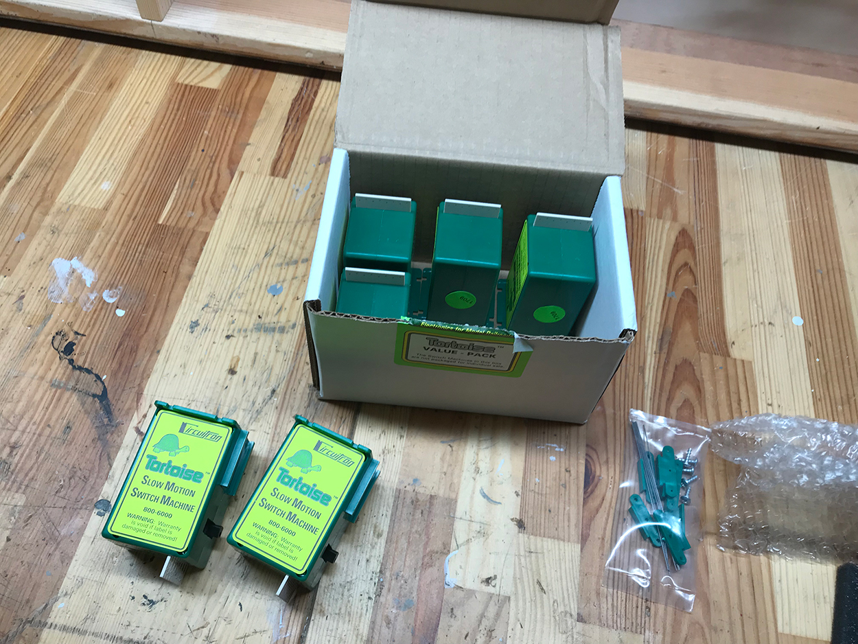
With the two/three buses now fitted and powering all the track it was time to start fitting the turnout motors. I decided to use Circuitron Tortoise switch machines and purchased a set of six from Ebay. I paid around $16 per motor.
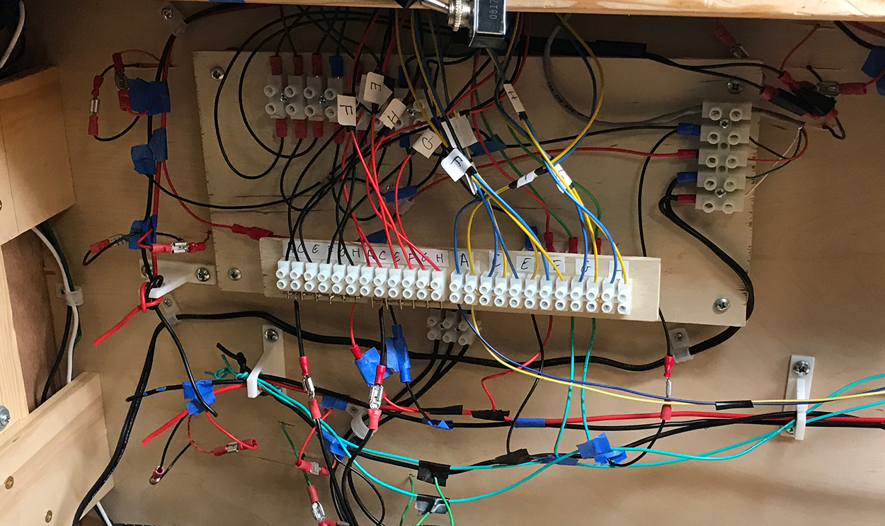
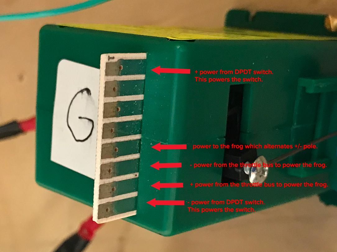
If you’ve never used a Tortoise machine or powered up a handlaid turnout it can seem quite a hill to climb to figure out the wiring. Not only are you powering the motor to switch the turnout but you are also sending power to the frog of the turnout which has to switch poles depending on the direction the points have been set to. It’s been a couple of years since I last did this task so I went online to double check the power inputs.
The motors rely on a 12 volt system separate from the controller and therefore my first task was to get that rigged up using a small 12v DC adapter. The layout now has three separate wiring systems:
- A mains AC system for the lighting and the internal power adapters
- A 15v AC system which then converts to a 12v DC system for the throttle
- A 12v DC system for the turnout motors and miniature lighting around the model.

One this new power source was installed I tackled each stage one at time and just mass produced each set of components.
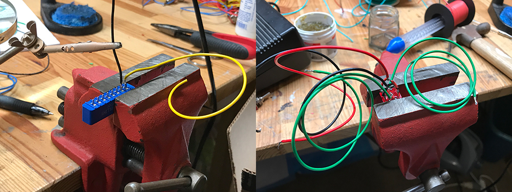
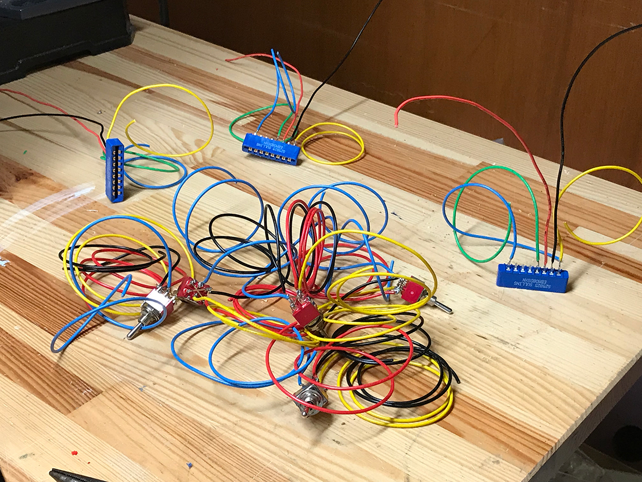

anyhow each switch took about 30 mins to fit and 30 mins to power – so 1 hour per machine. I did the work over two weekends. It was tiring and stressful and not much fun. Nevertheless after fixing a few minor shorts and other small gotchas the whole system worked really well. My little locomotive was able to navigate the whole layout with ease.

Anyhow I am really glad this stage is over but I’m not quite ready to start modeling. I still have to build the exit points for the track to connect with the cassettes and also finish off the control panel (it needs a new diagram and repositioning of the brackets).
I’ll get to those in the next week or so and then I’ll be ready to start with the structures.