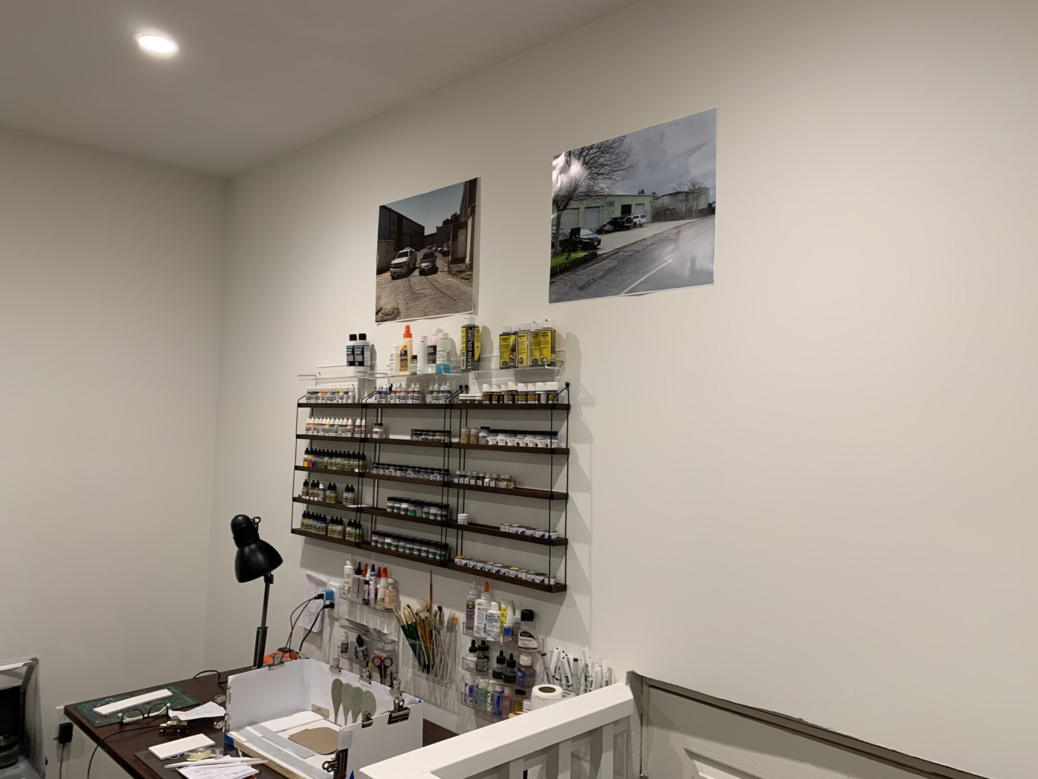
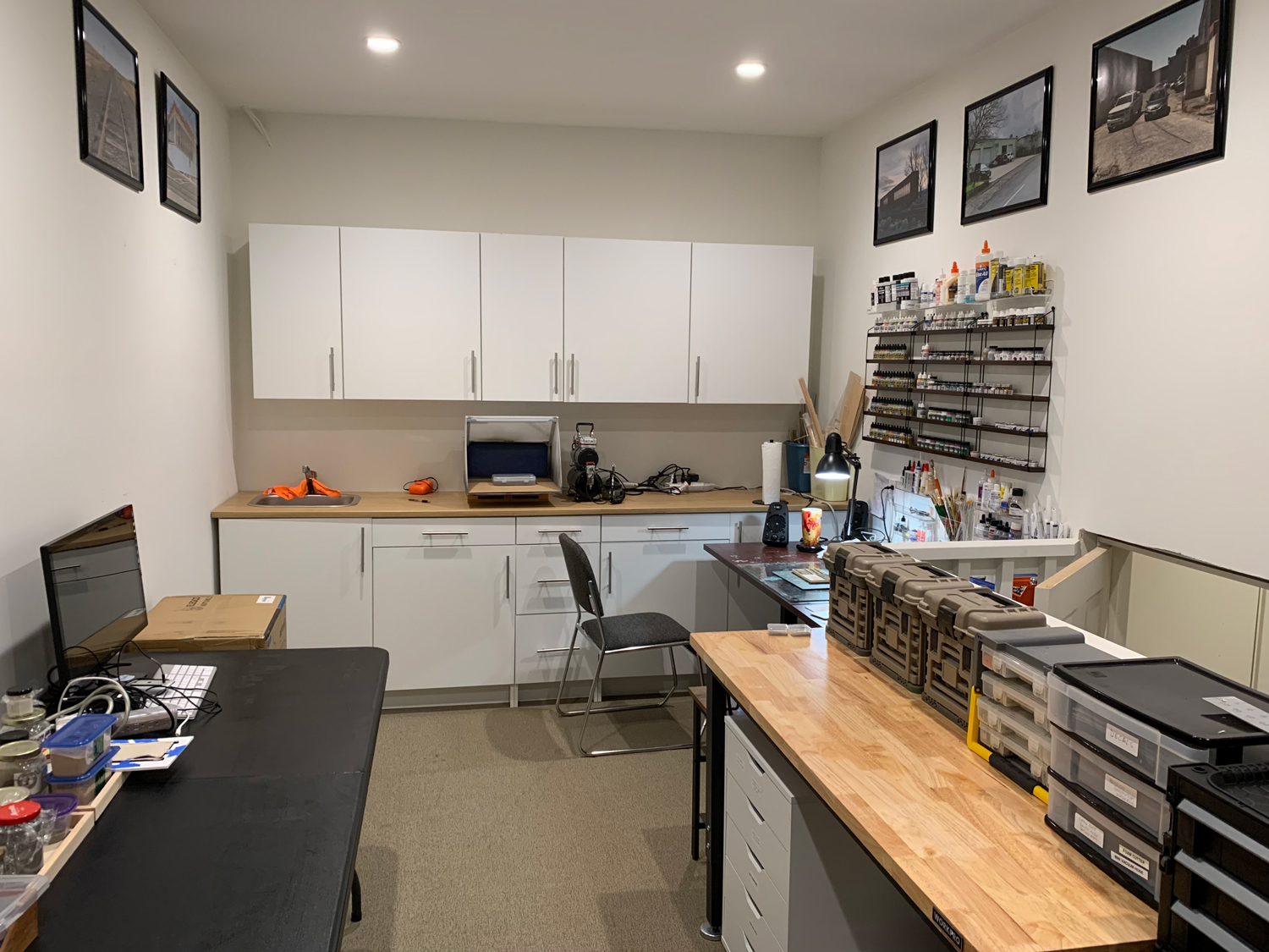
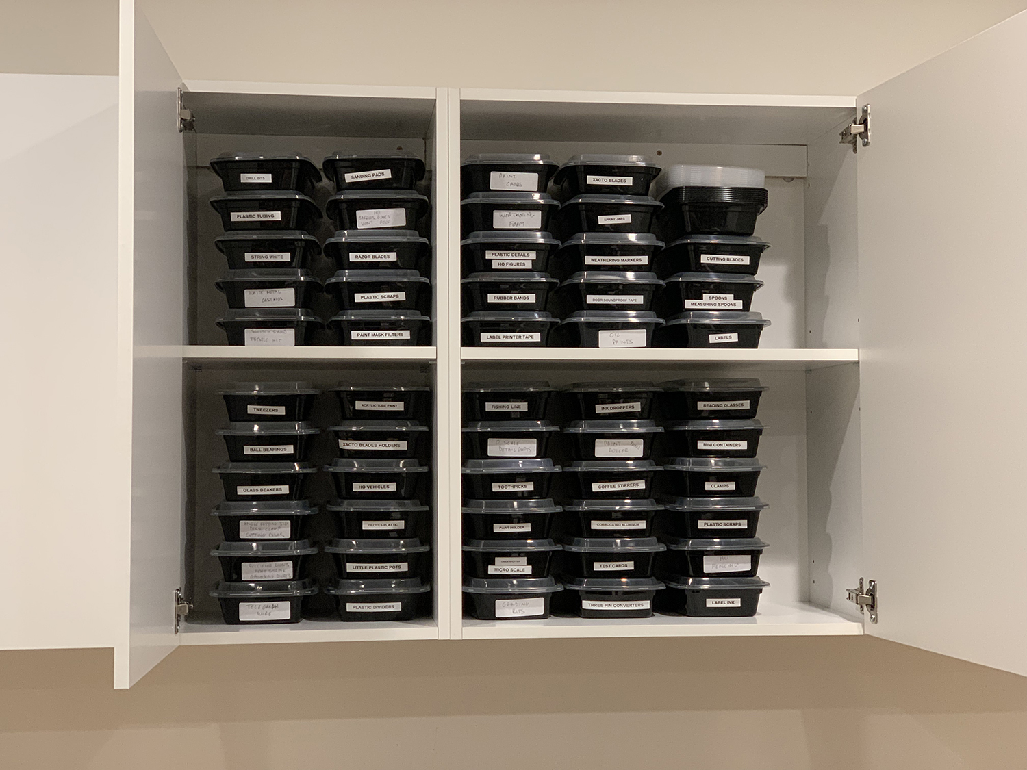
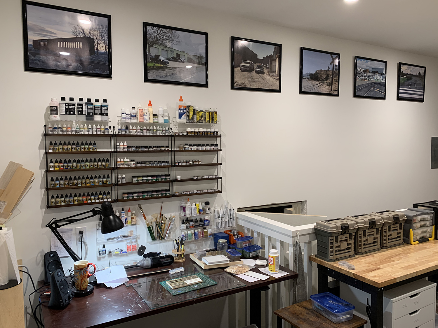
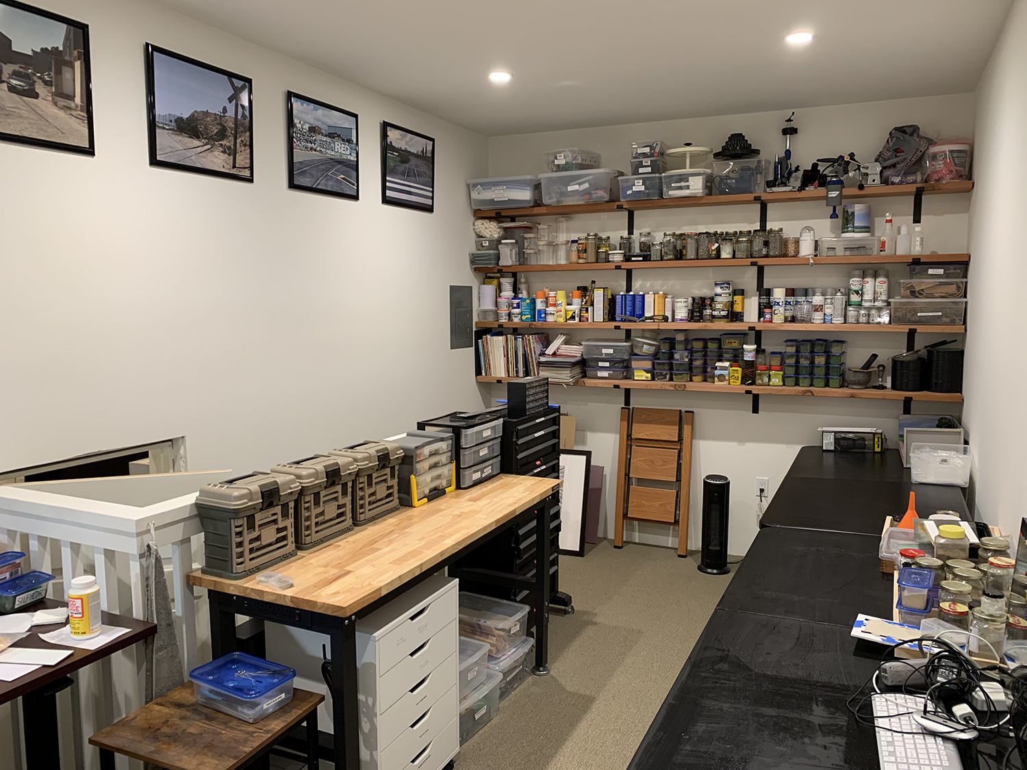
My work folks finally finished installing the kitchen units in the modeling room. I now have plenty of storage for my mini-tools, a work surface for my spray booth, hot and cold water plus a sink. I’m happy to see the whole room finally come together especially as year ago this room was just a dusty shell. I still have to add some more pictures and more paint storage racks and I will get to that in the next couple of months.
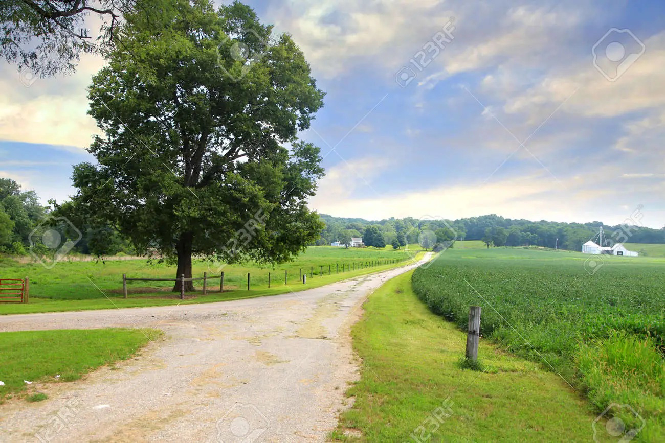
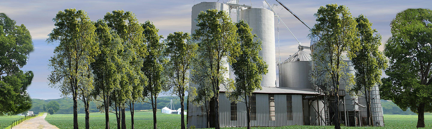
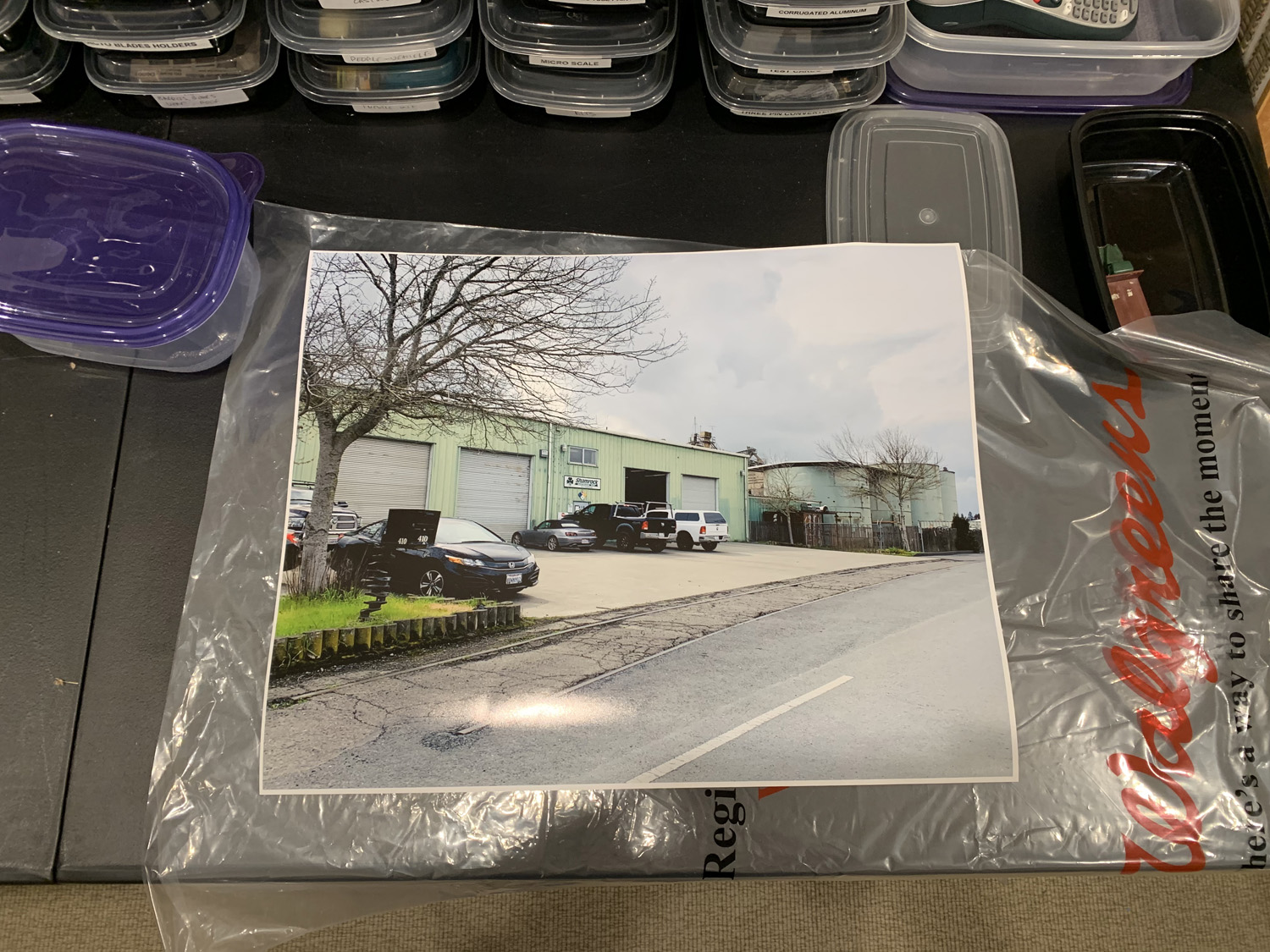
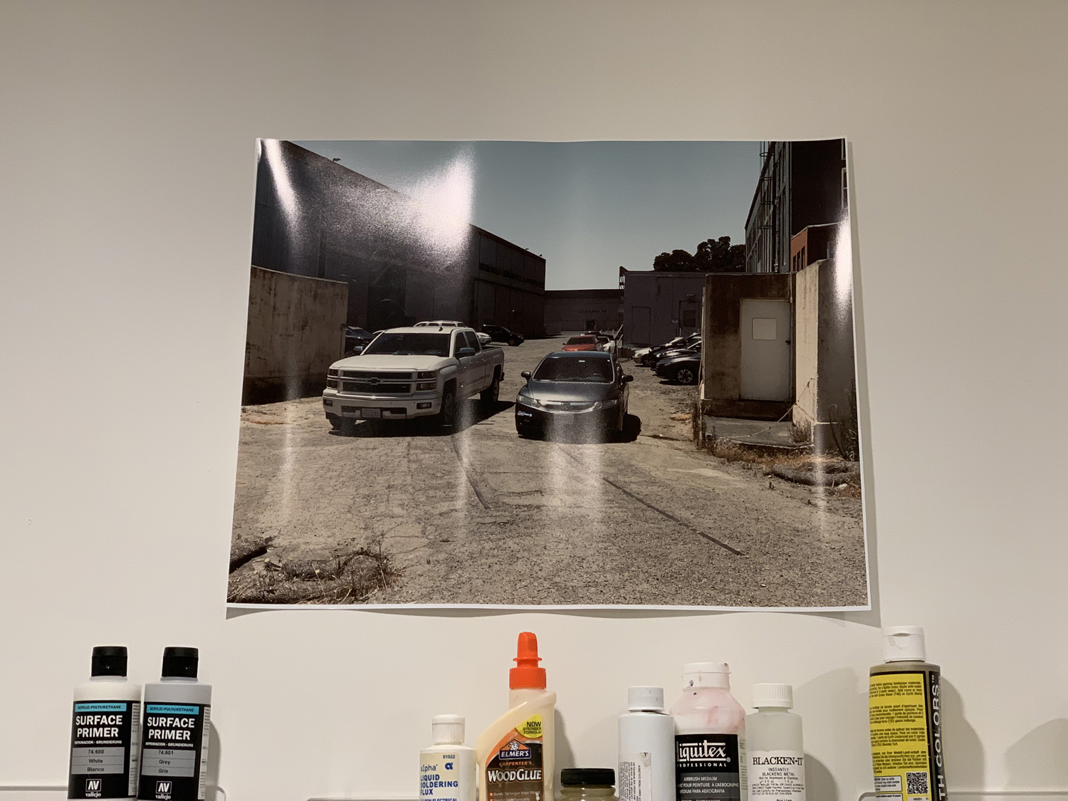
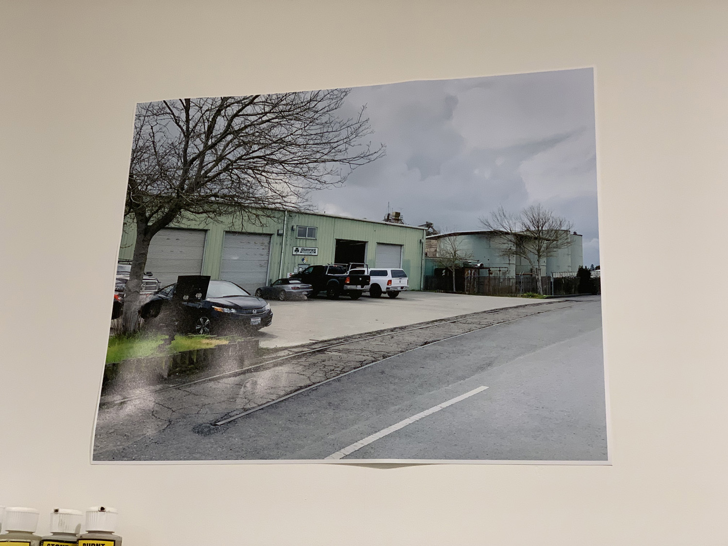
Sandy gravel road
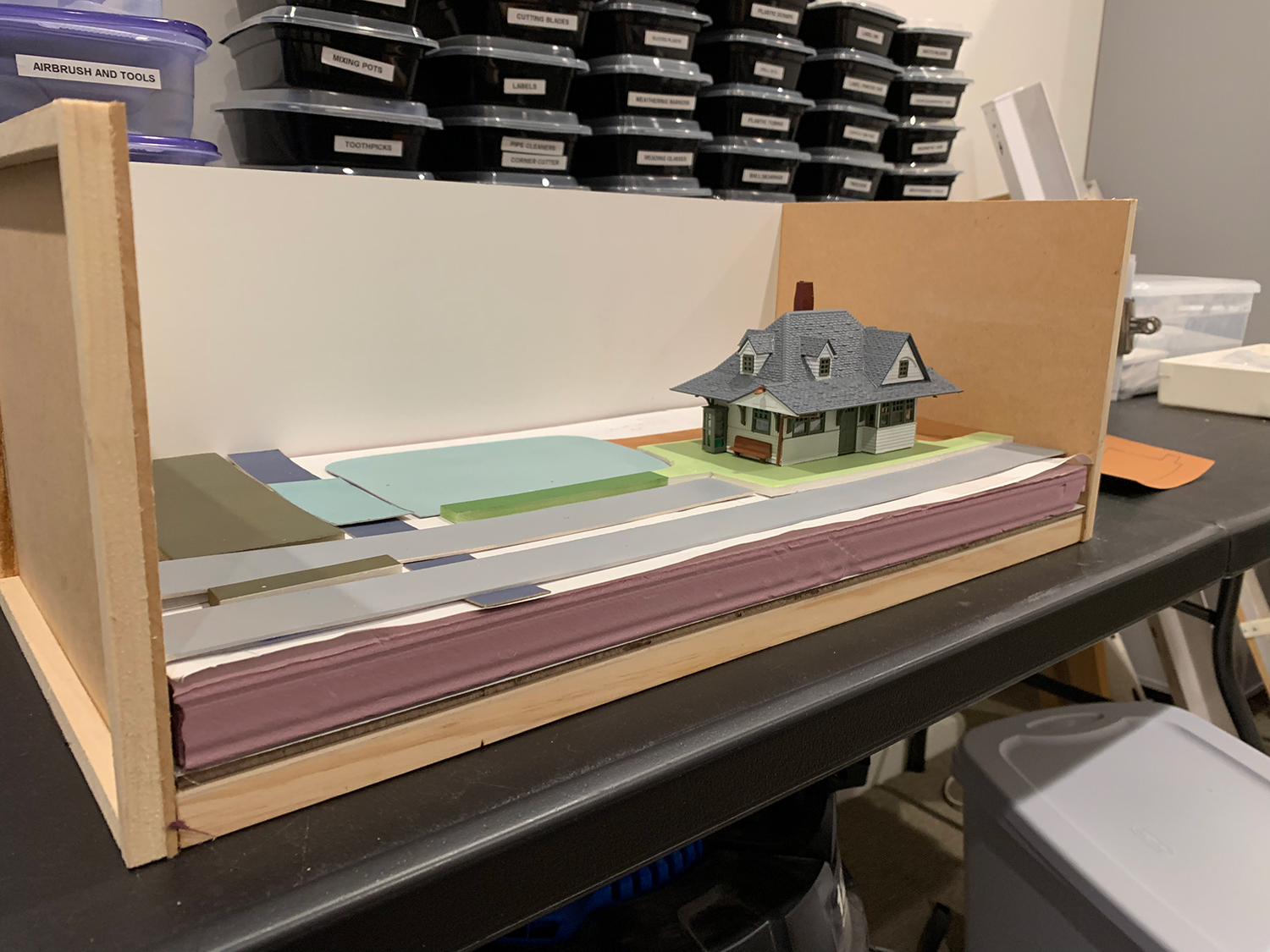
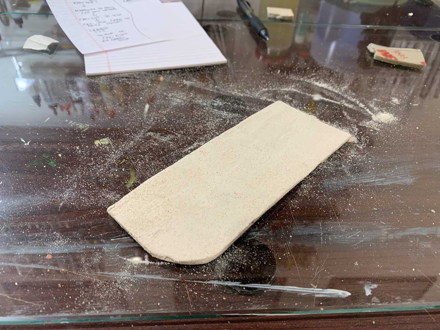
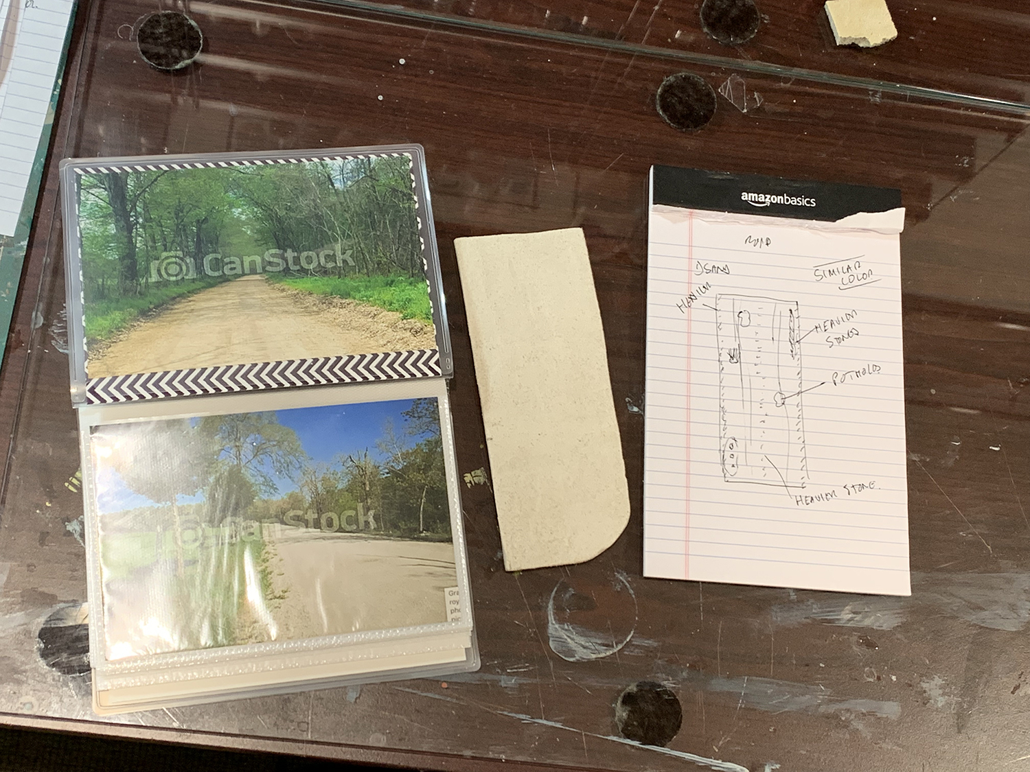
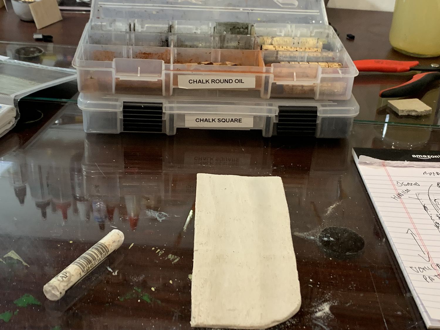
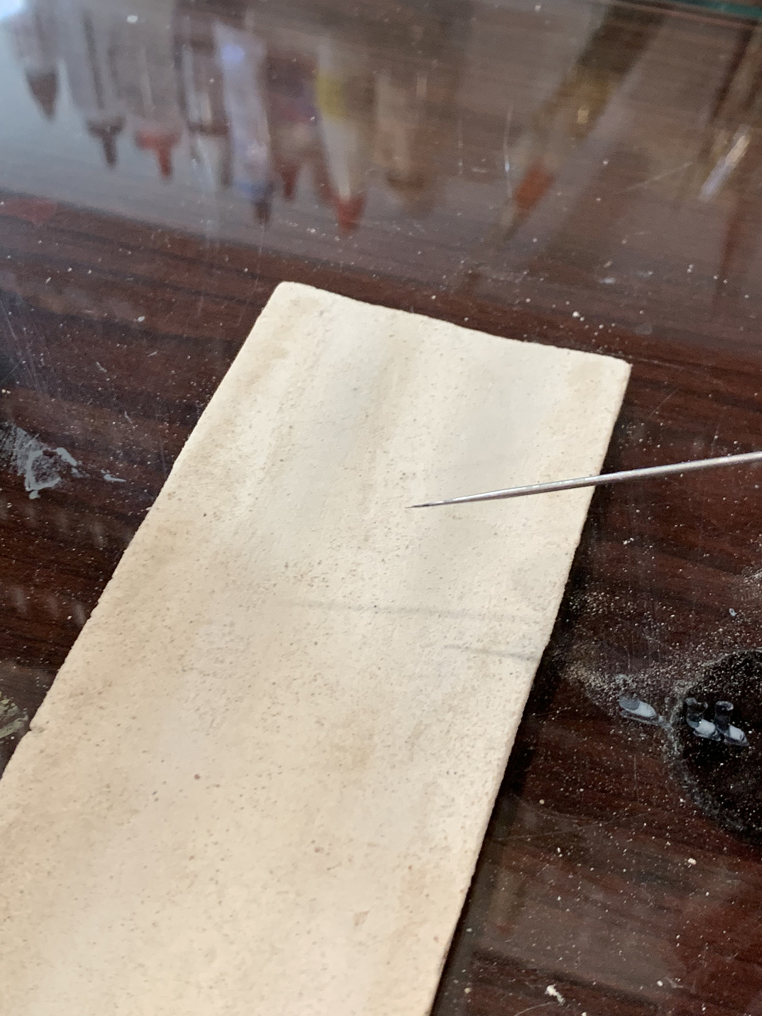
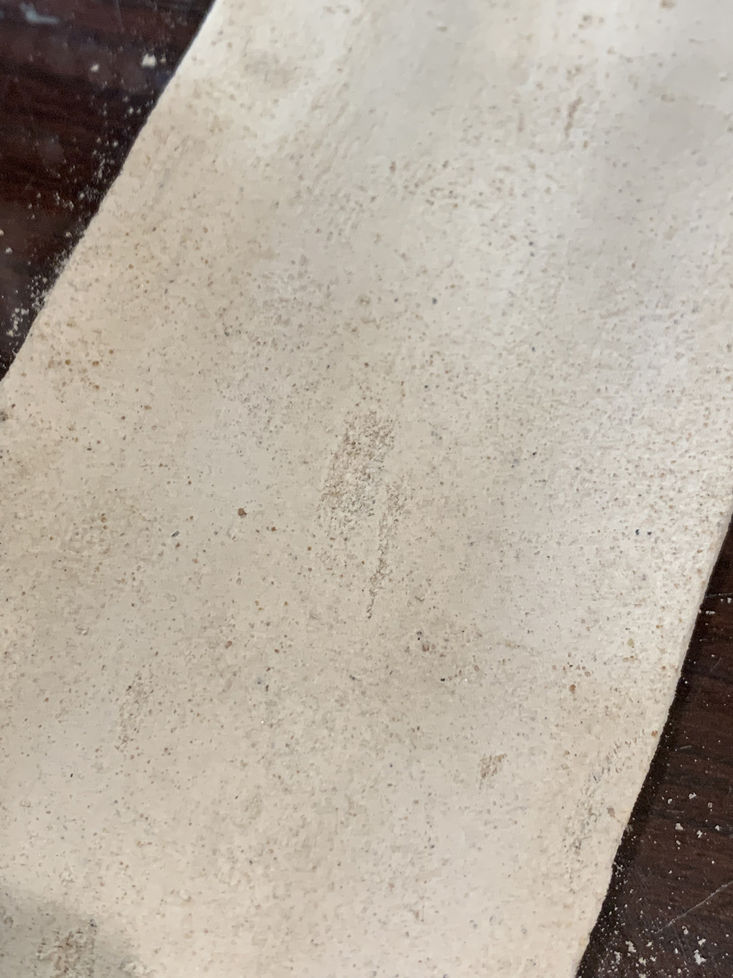
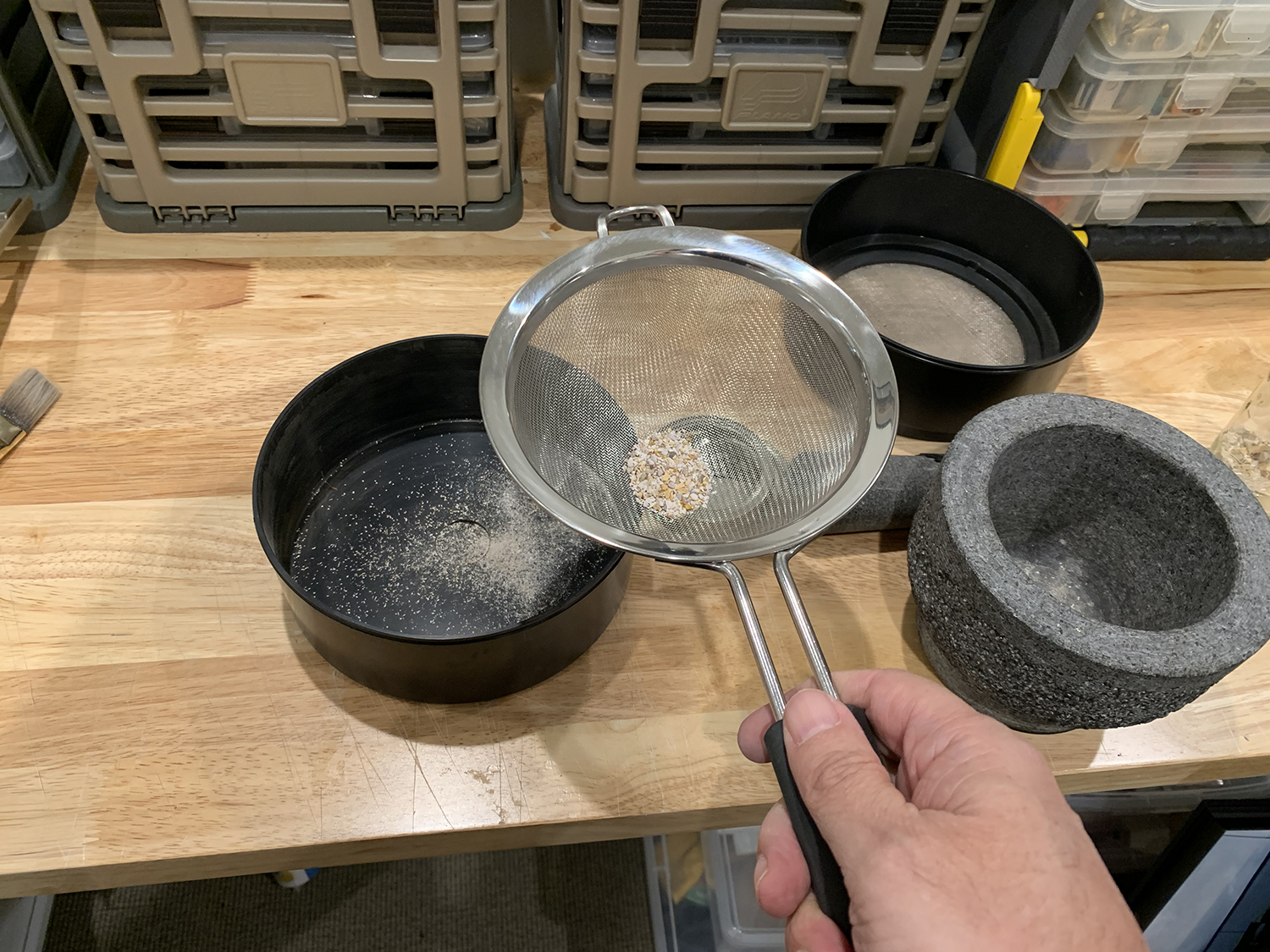
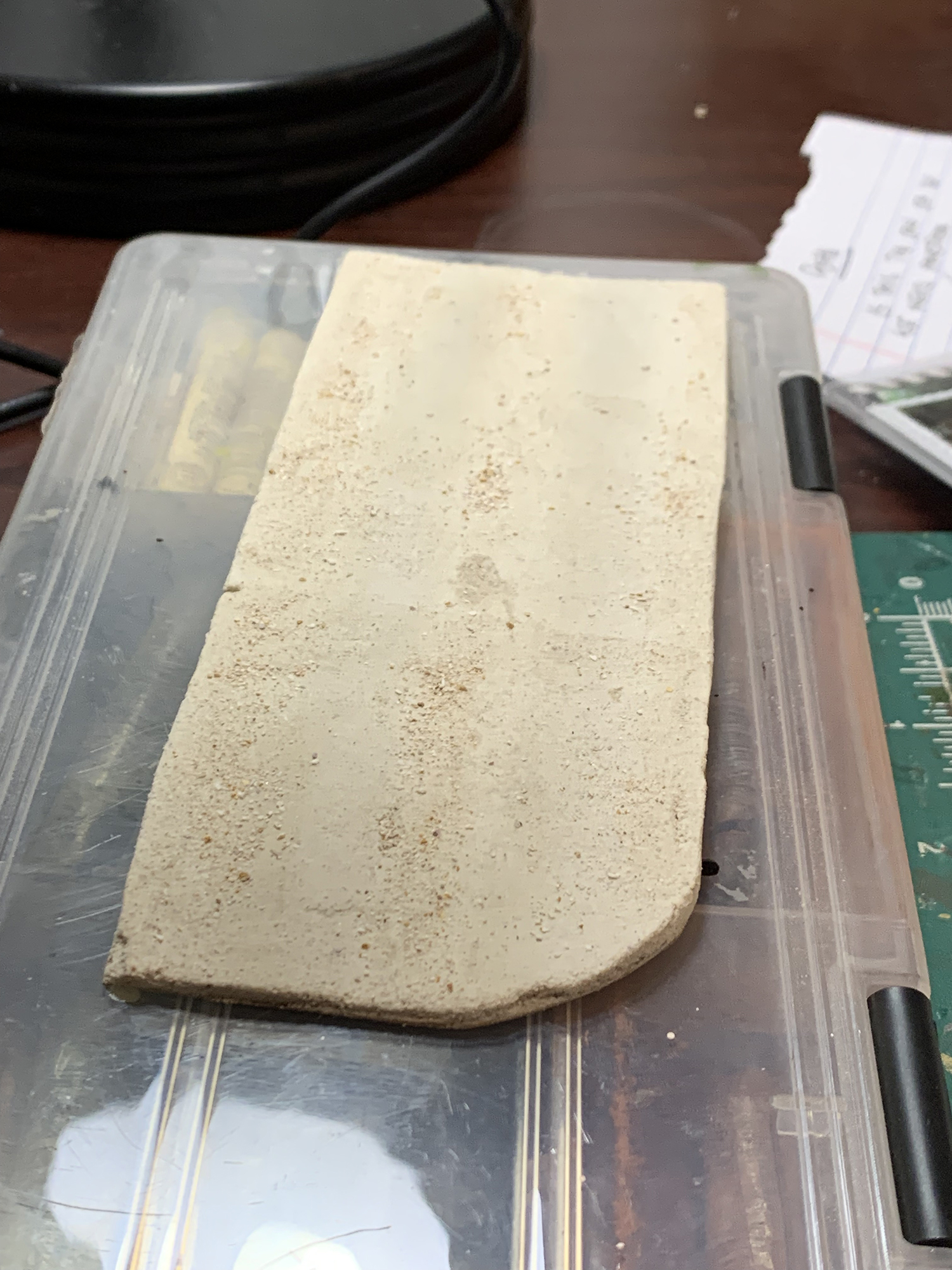
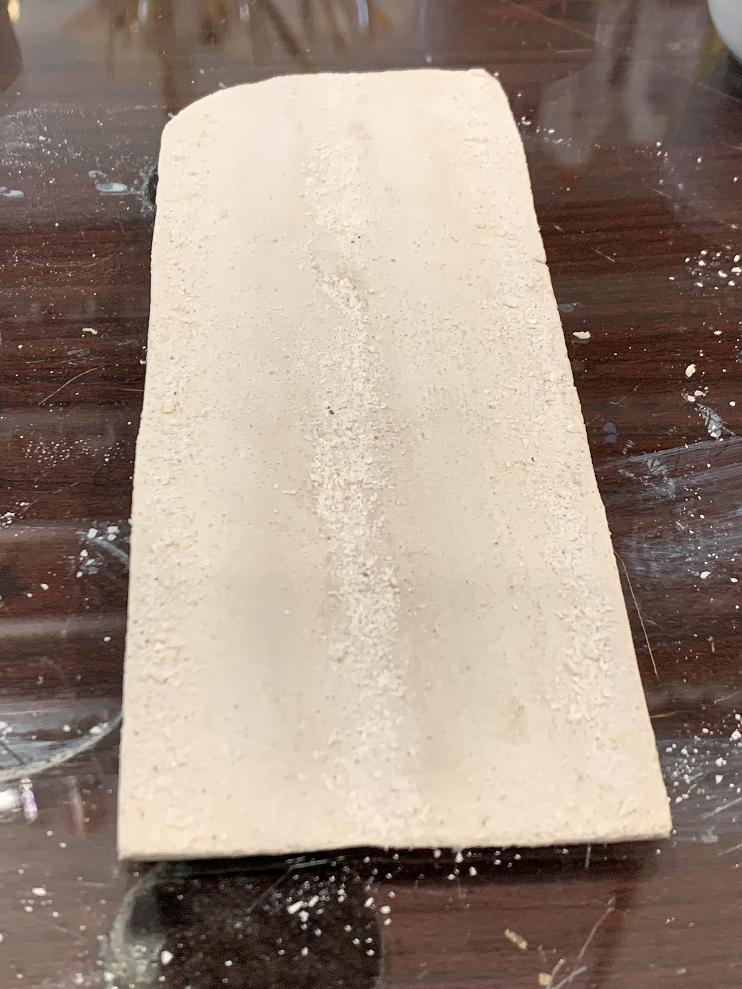
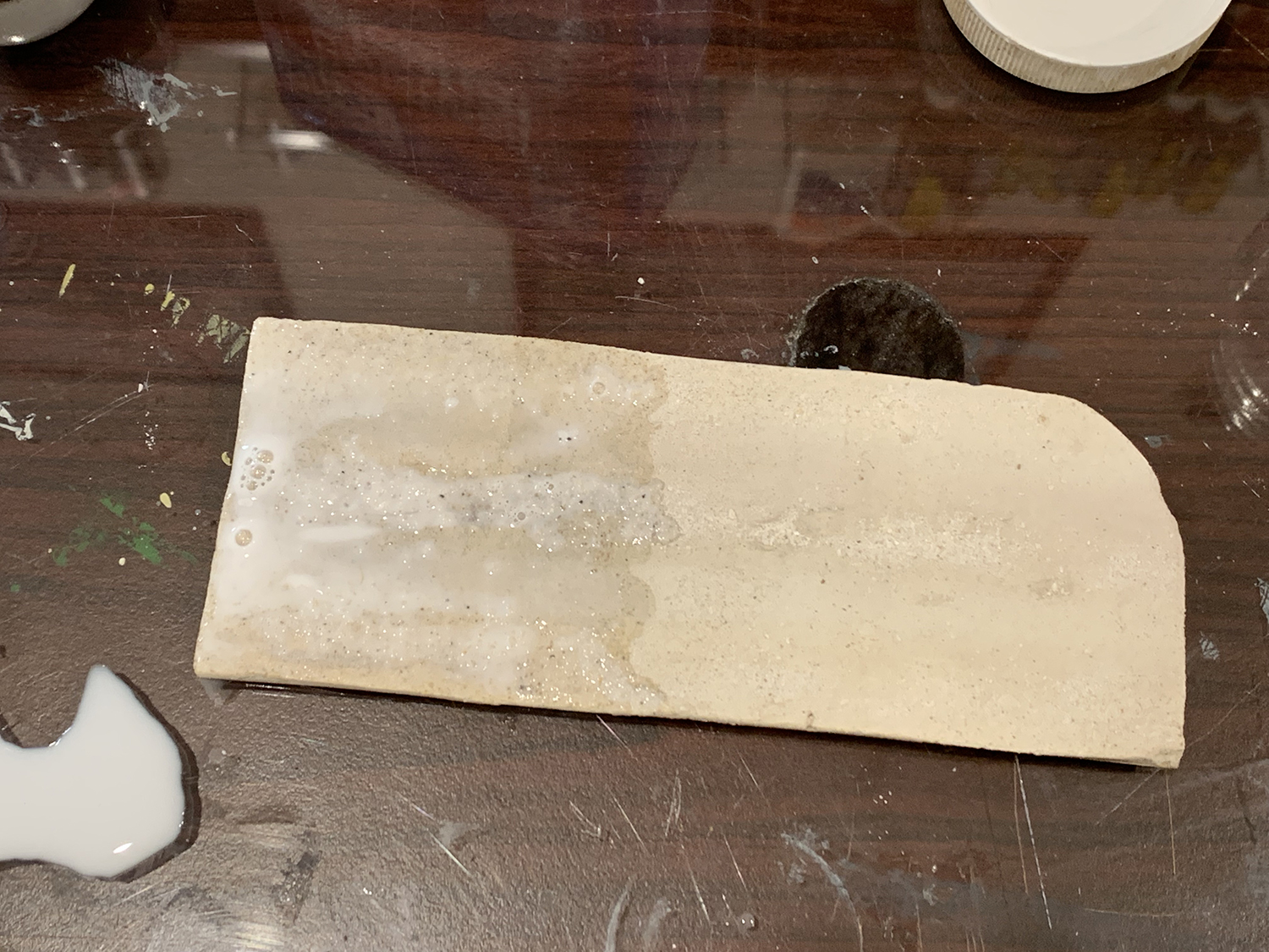
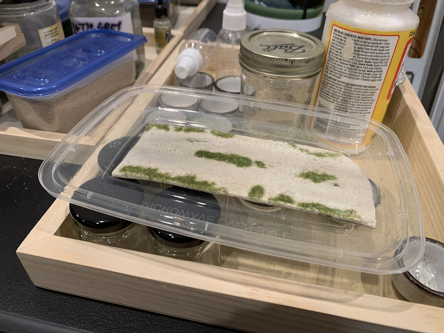
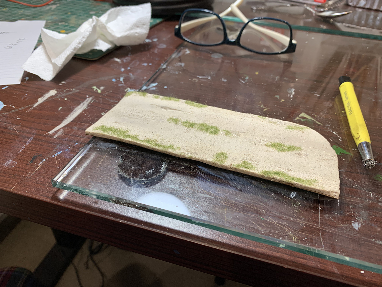
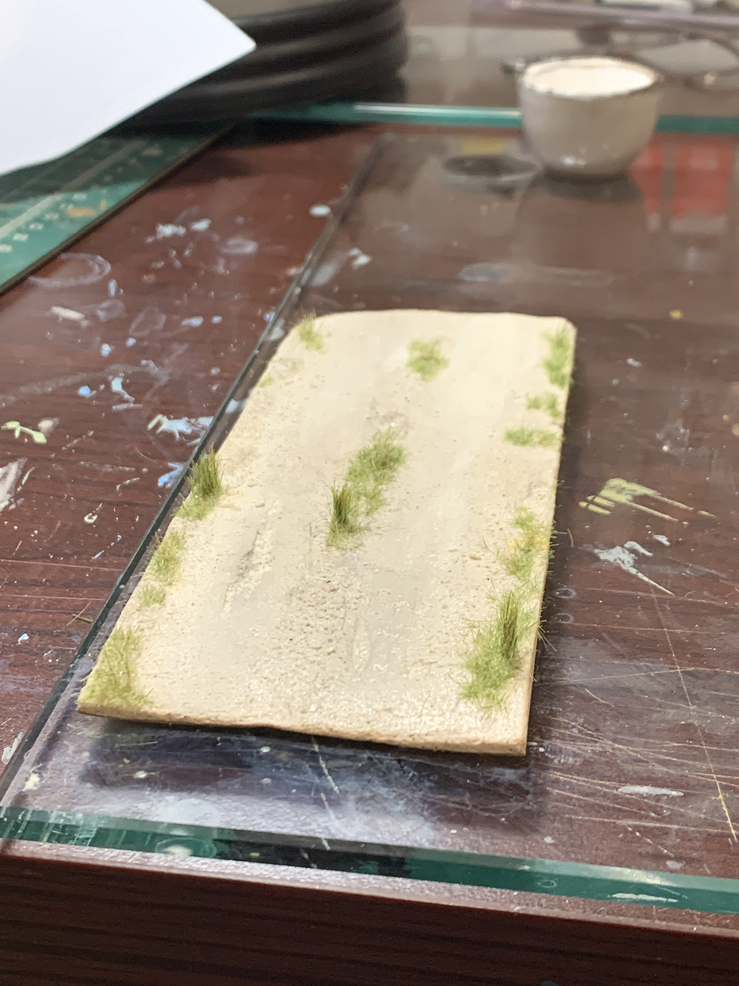
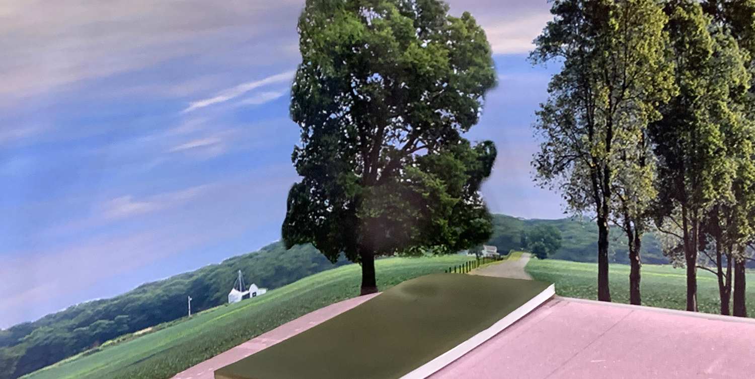
I continued working on the gravel road. The thinking behind the work is that I wanted to try to keep things as clean as possible with not too much weathering or contrast or change of color. I wanted to add different textures of a consistent color and just use different shades of that color: eg use a base color and have it be a little darker at time or a little lighter at times but never using a new color. The base texture is the original foam putty mixed with sand as described earlier – now it was time to add stones, rocks, sand etc.
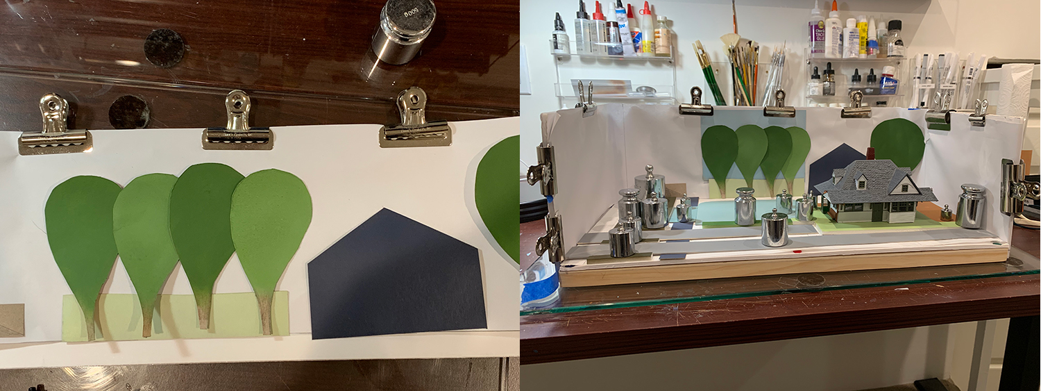
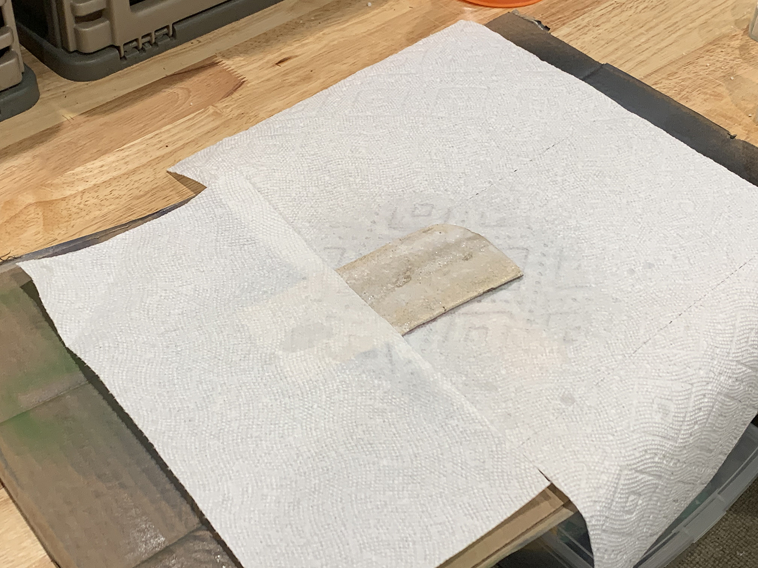
I stuck to my rule of practicing and searching for materials, methods, and techniques before committing the final build to the model and as such these next pictures describe a test – not the final. The lessons taken I from this test will be put to another attempt (already begun) next week.
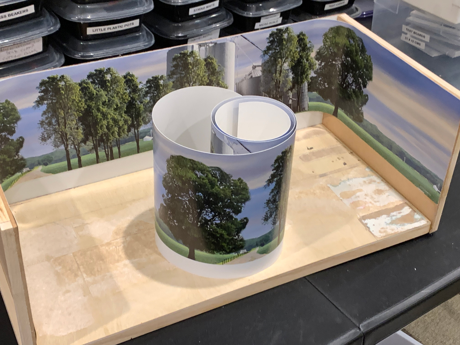
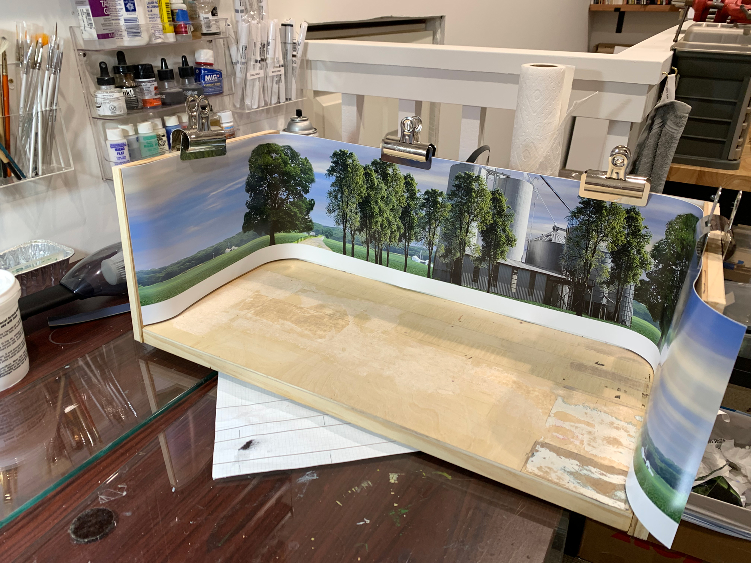


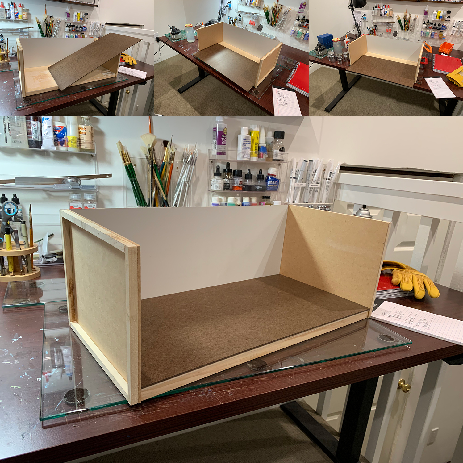
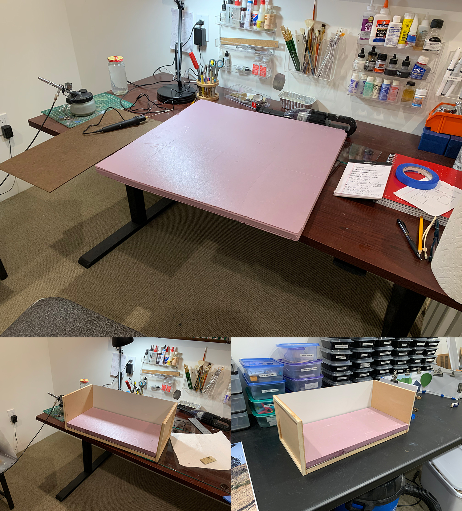
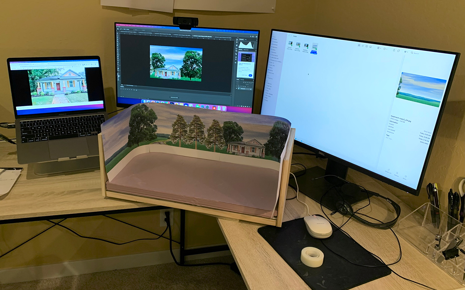
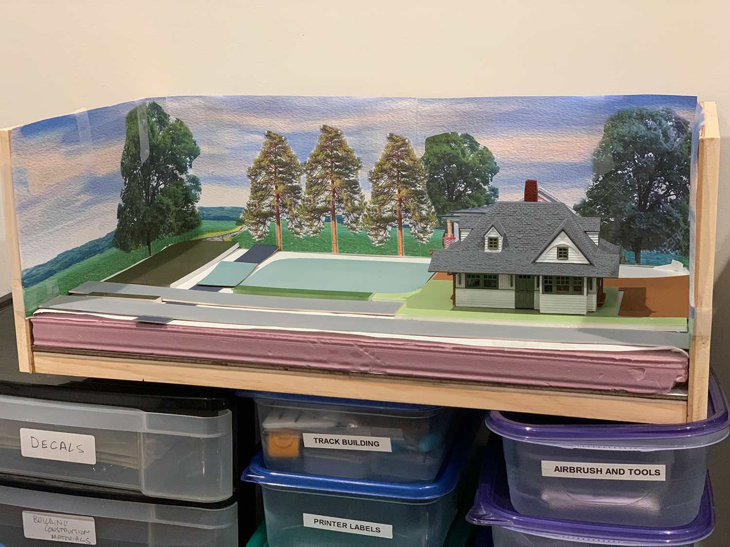
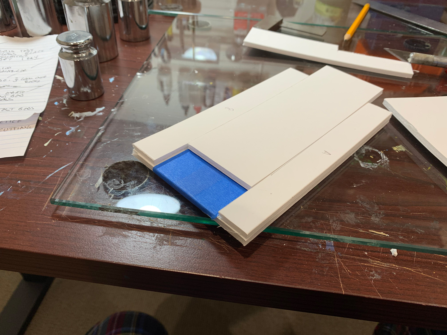
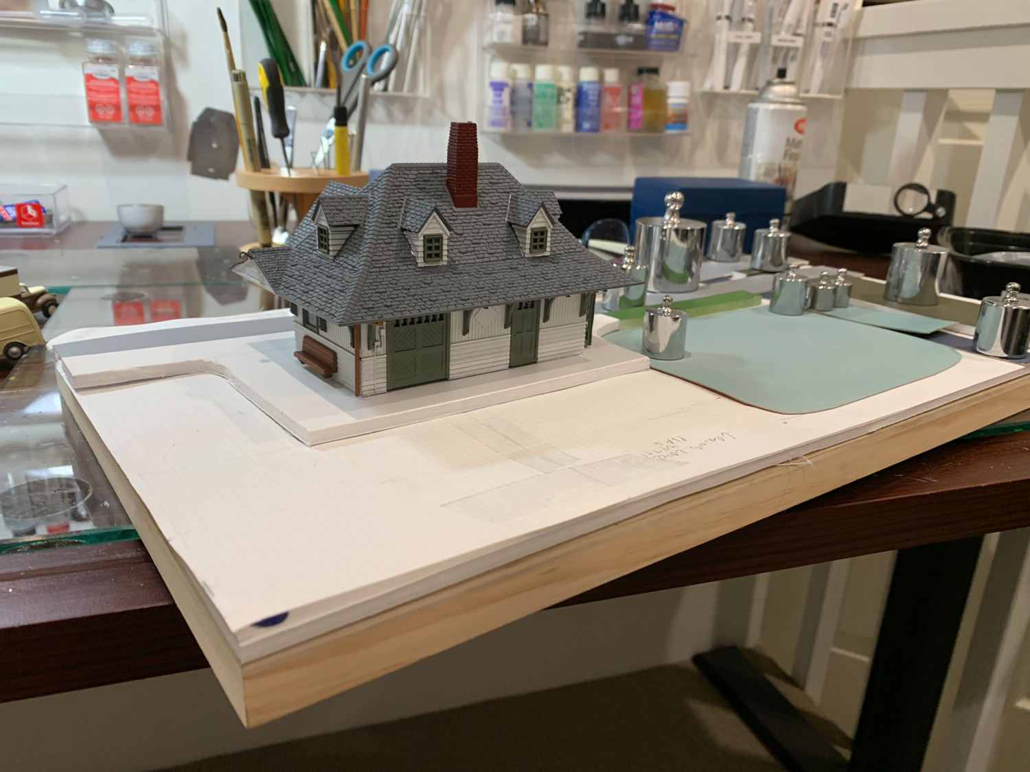
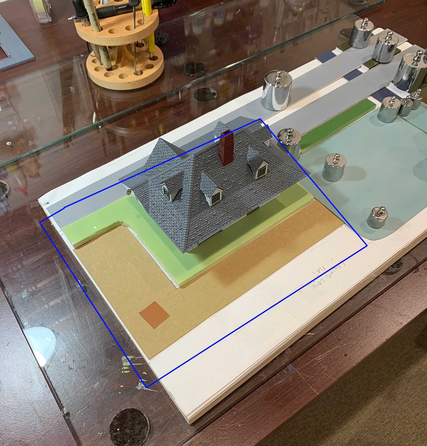
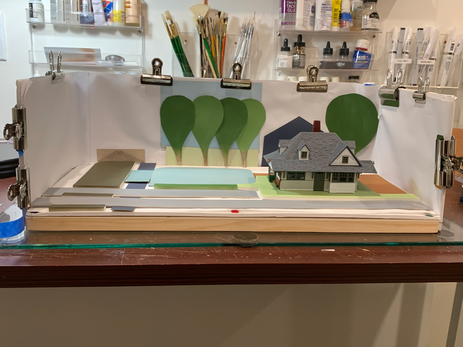
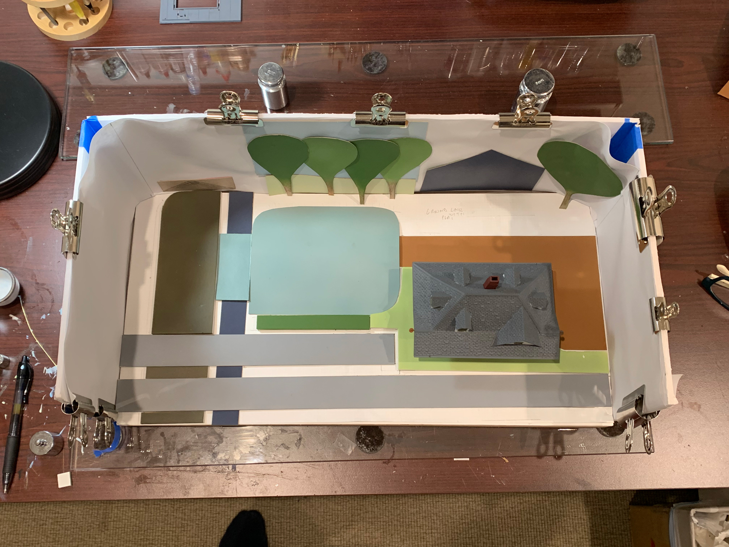
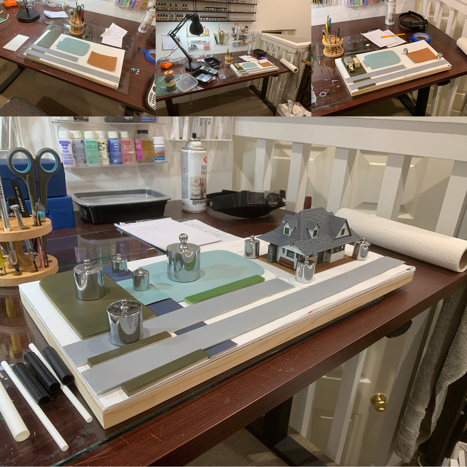
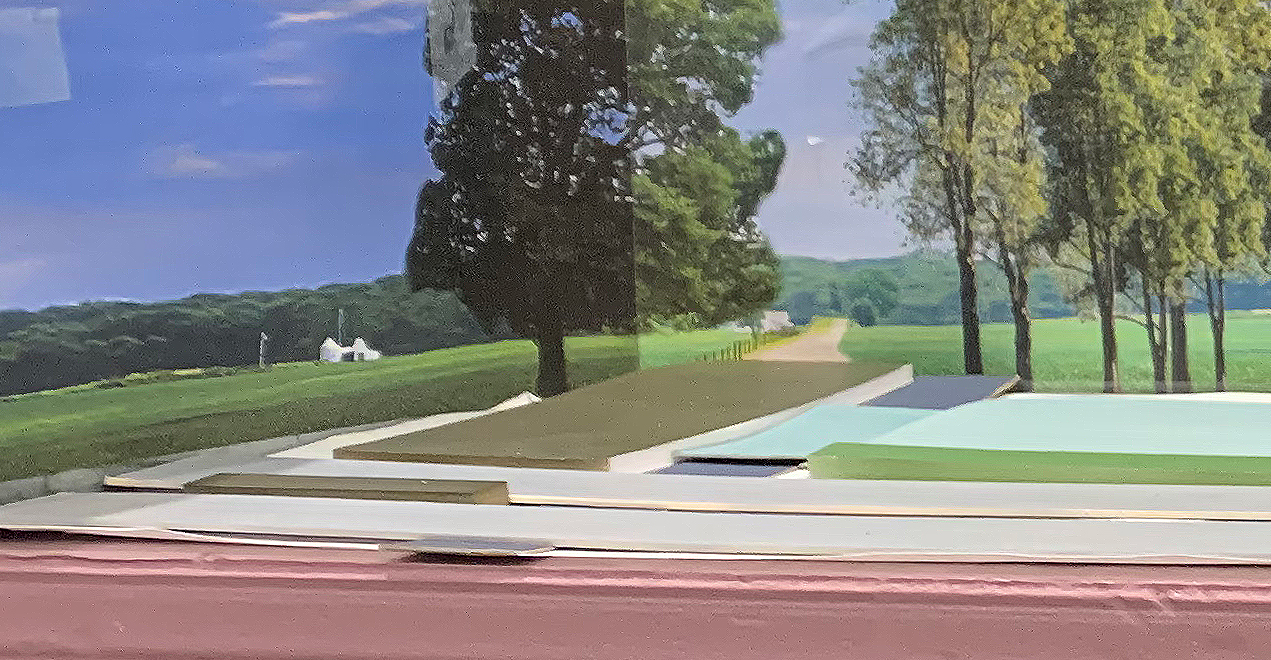
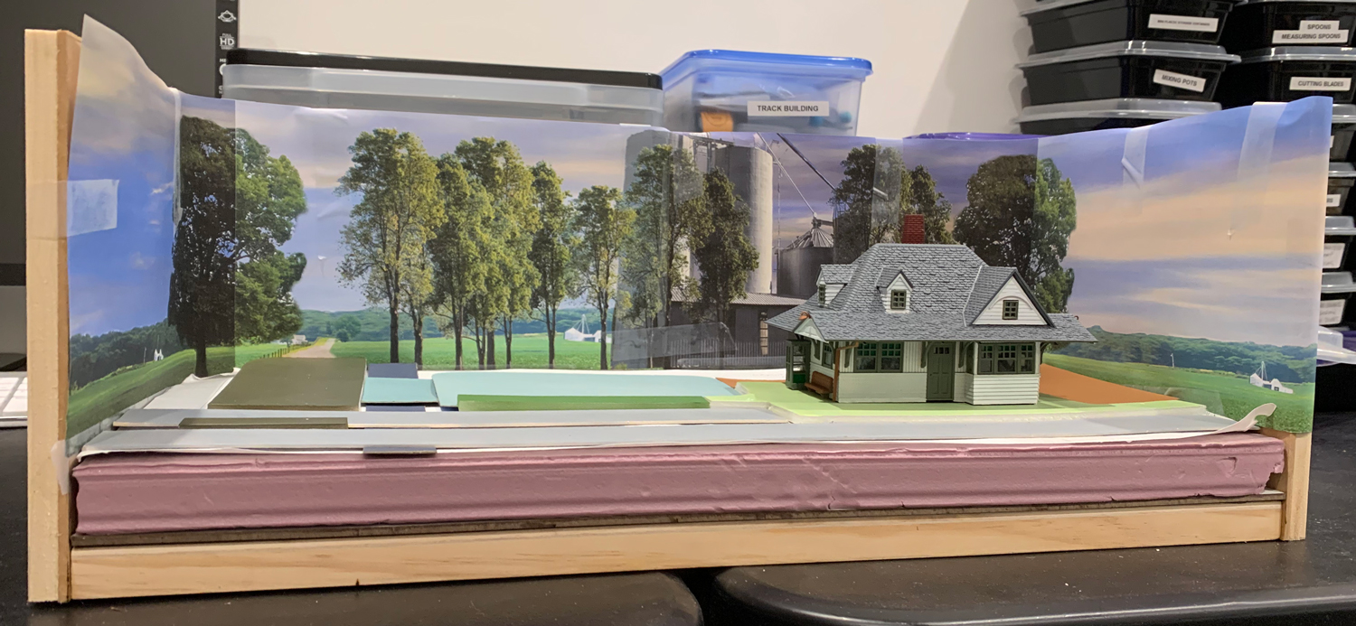
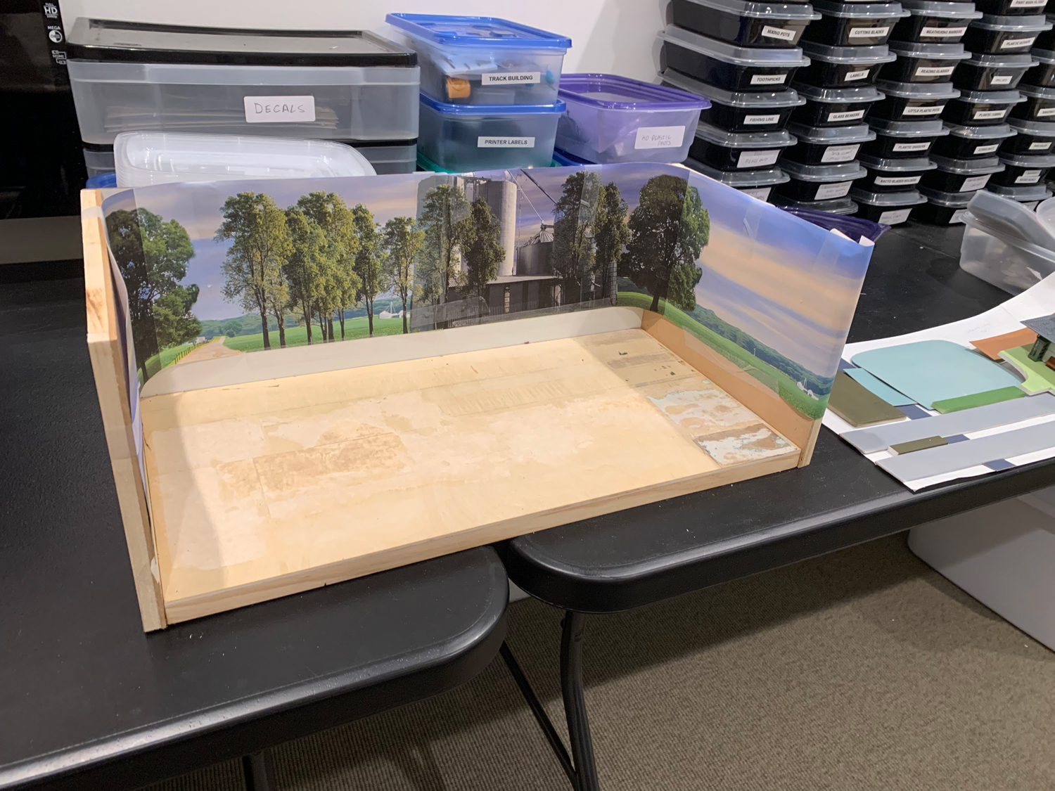 The backdrop frame is built for the base to be moved into place when the modeling has been completed.
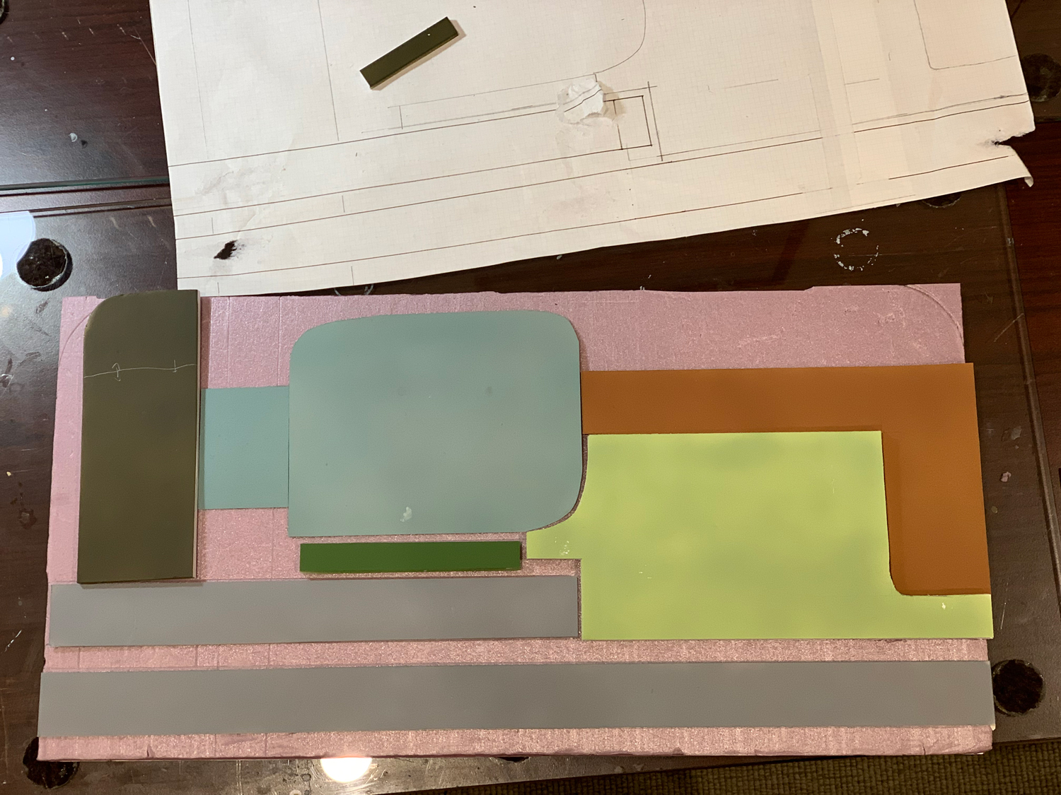
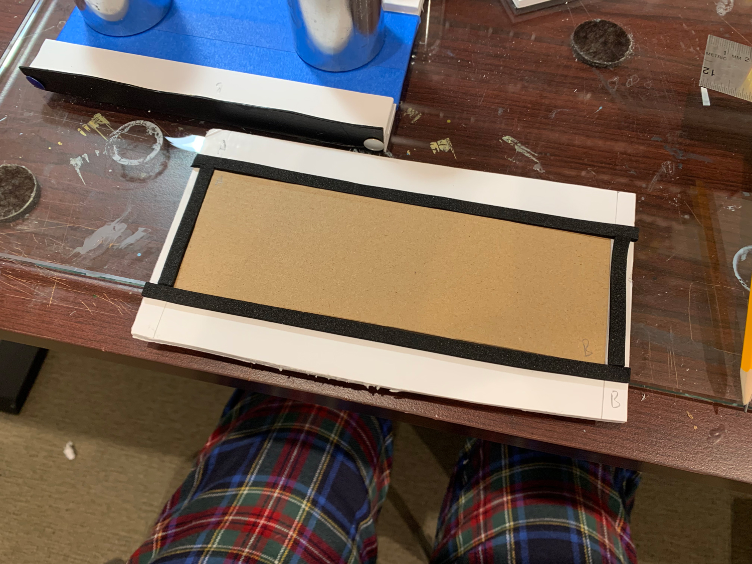
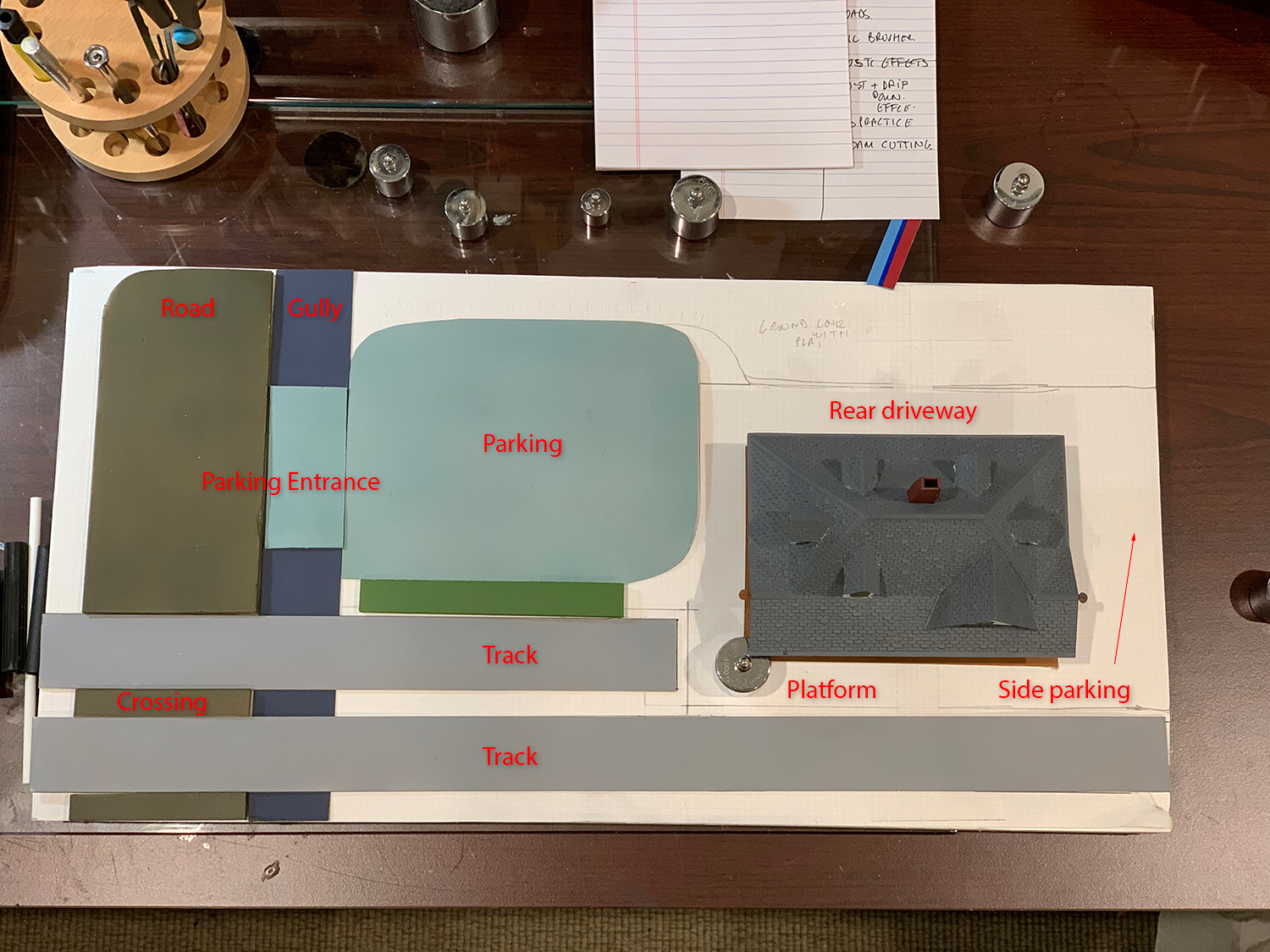
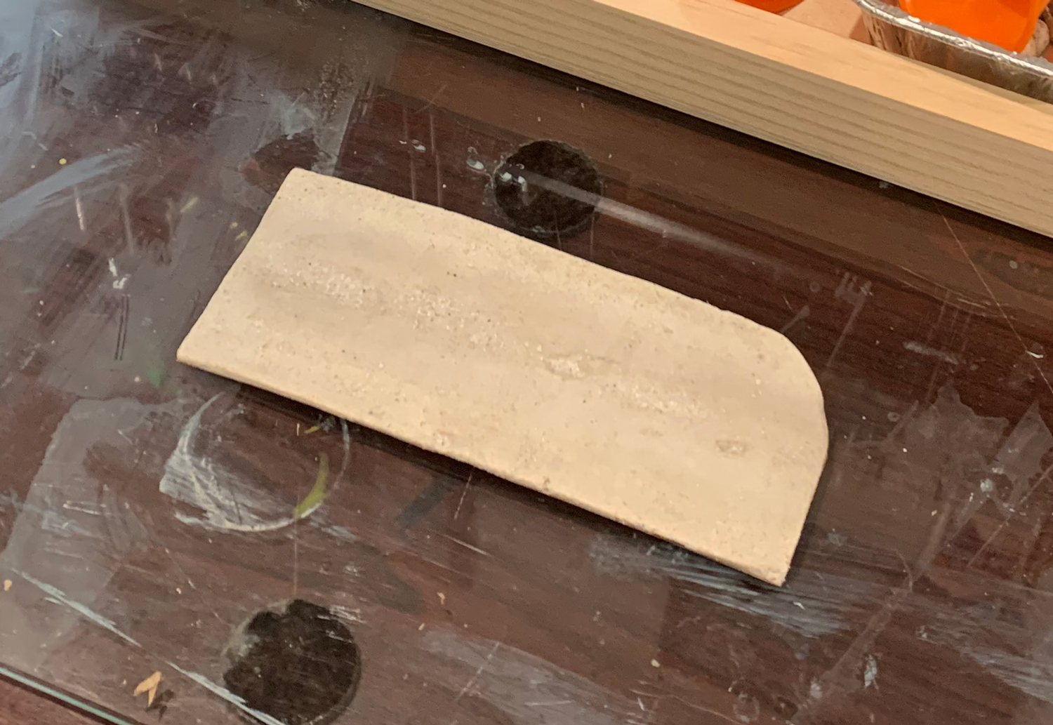
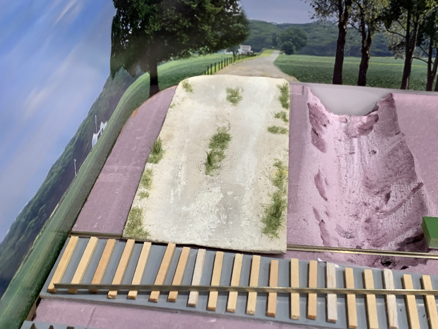
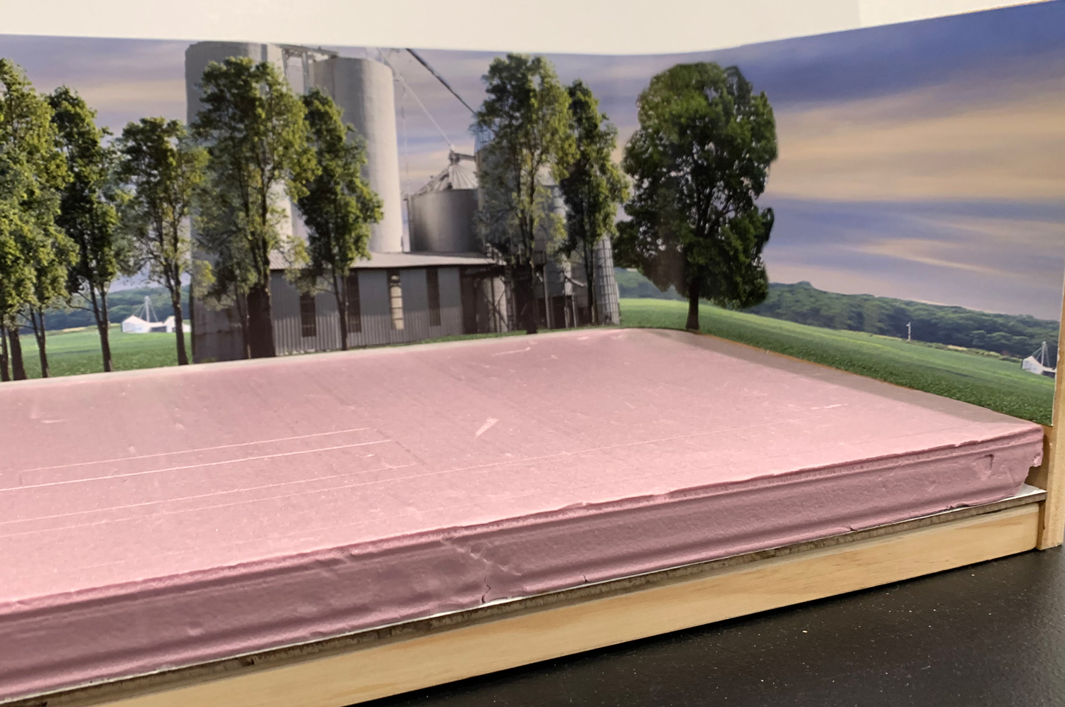
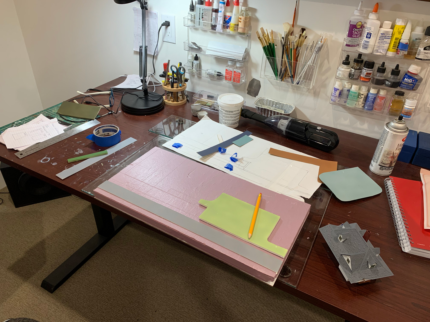 I glued the foam base to a piece of hardwood and first step is to build the road and the ditch alongside. I’m trying to figure out if I should stick the track onto a card base or just lay the track directly to the foam.