I had decided a while ago that I was not going to settle for second best when it came to The Town module. I’m not in a hurry to get things done and I really want to make sure I’m 100 percent happy with each stage before moving on to the next.
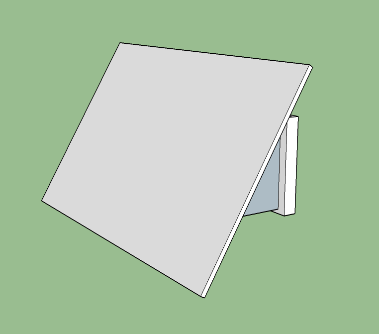
I wasn’t happy with the first box that I built. I felt it was unnecessarily bulky for such a small layout. I decided that I wanted to keep the design of the box very simple – just the basics – a firm flat surface for the switches with a couple of angled supports to join it to the main board. I did a new design in SketchUp to get a feel for what I needed and then built a foam board demo.
This is my first attempt. I added a couple of hinges on the inside so that I could pull the cover forward to do maintenance. The biggest issue then became how to join the box to the main board.
I couldn’t figure out how to join the angled brackets to the main board – screws? glue? What about maintenance? The box needed to be removeable for access to the switches but it also had to be firmly fixed to the board. I didn’t want to use angle brackets as they just don’t look good. After a few days pondering the problem I had a lightbulb moment! Why not design the brackets in SketchUp and have them fabricated in hard plastic by Shapeways?
This is what I came up with:
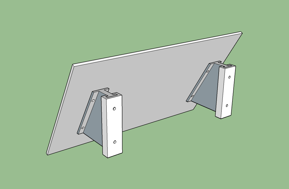
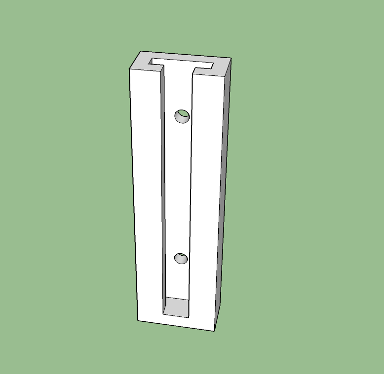
I uploaded the designs to Shapeways and ordered them in firm white plastic. This material has proved in the past to be strong enough for this type of project. The cost for the four pieces is around $40. I’ll get them back in about a week.
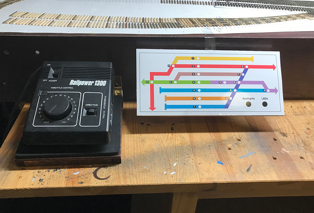
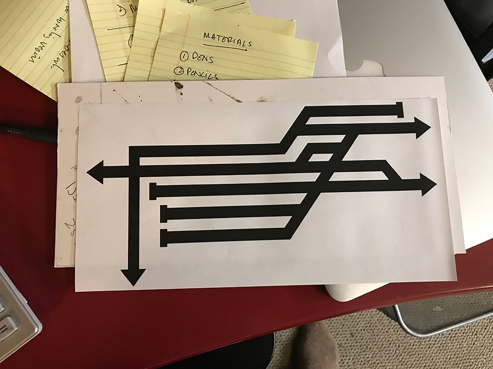
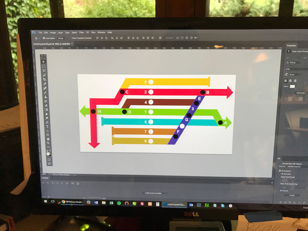
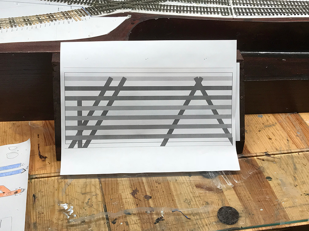
The controller diagram
My last attempt finally put me on the right track to really get the job done properly. I started the design in SketchUp and then transferred it to Photoshop to add some features. I quickly realized that I didn’t need SketchUp at all and could design the whole diagram in Photoshop quite easily. I’ve been using Photoshop vector tools for years so it made sense to use them for this project.
Here’s some of the process:
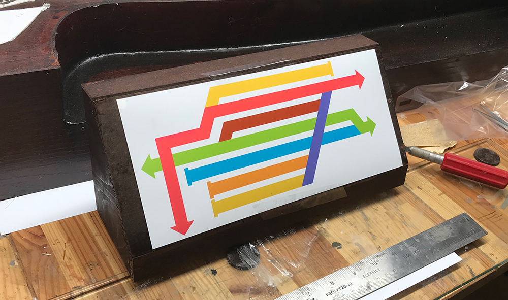
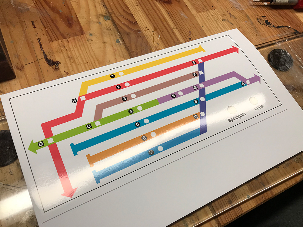
I added this to my little mock-up to see how it looked and overall I’m happier. It looks less sturdy than my original box but is more elegant and the size of the panel suits the module better. The proportions of the different components are more balanced.