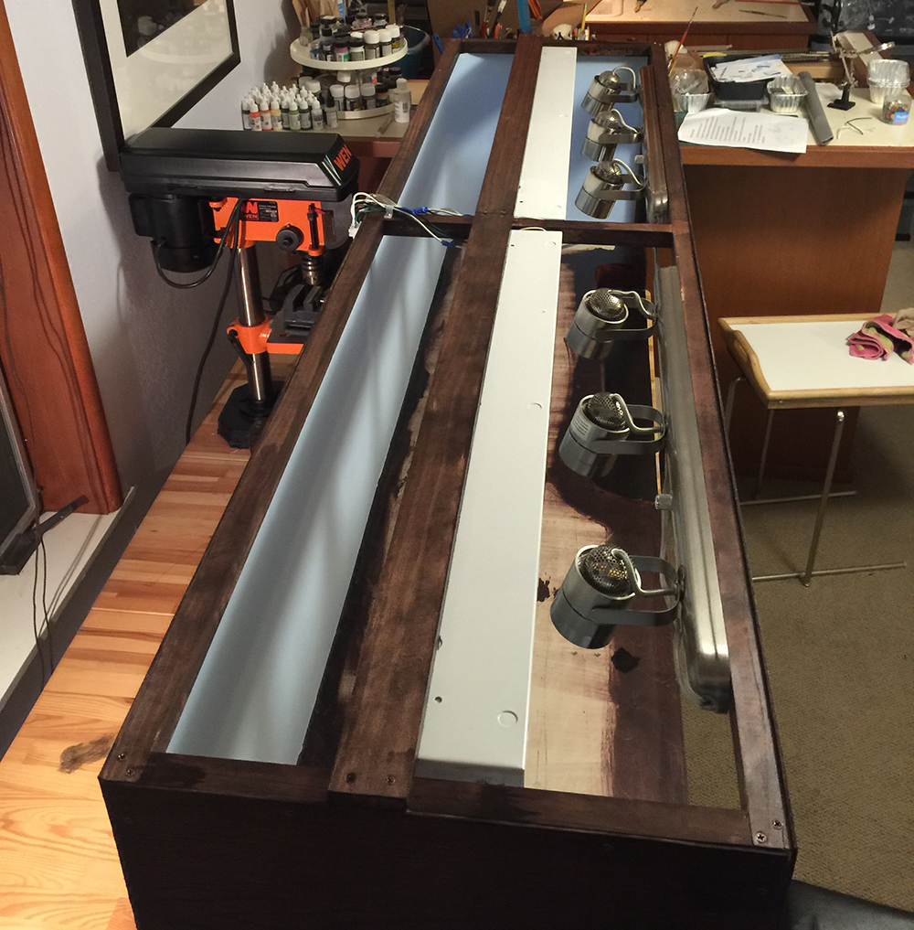
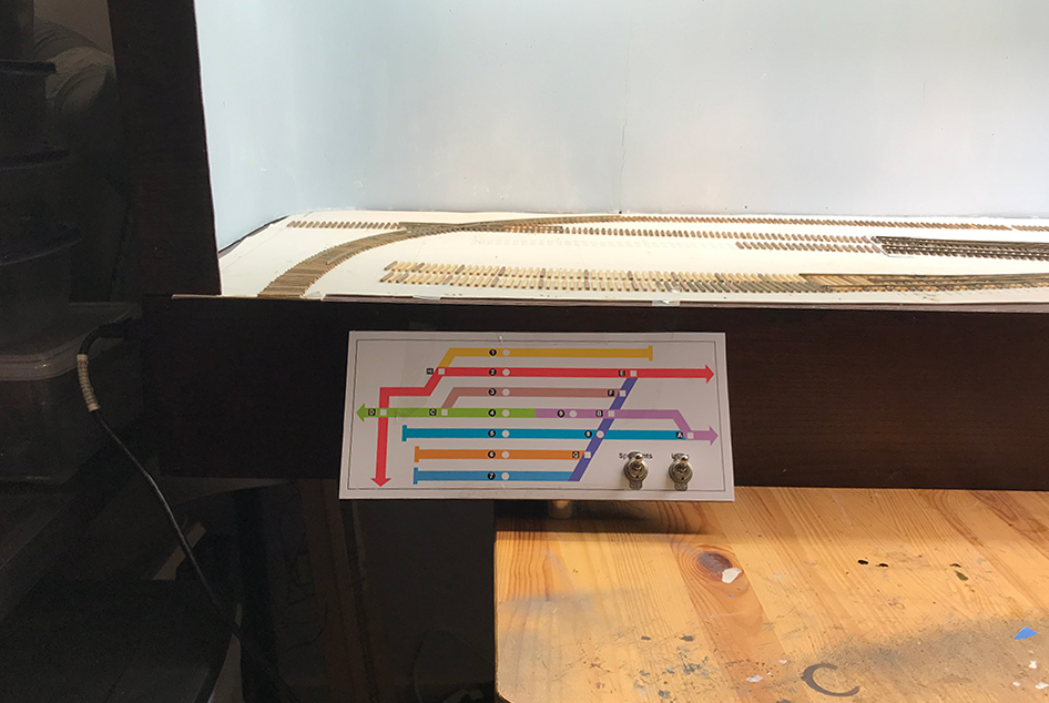
I managed to set up the internal AC electrical system which provides power to the DC adapter/s and the lighting system. I built the lighting system a while ago but had housed the switches in an ugly box that protruded from the front. I removed this and have now located the switches on the control panel.
I’ve covered the lighting system in the past but as a quick reminder here are some pics of the process:
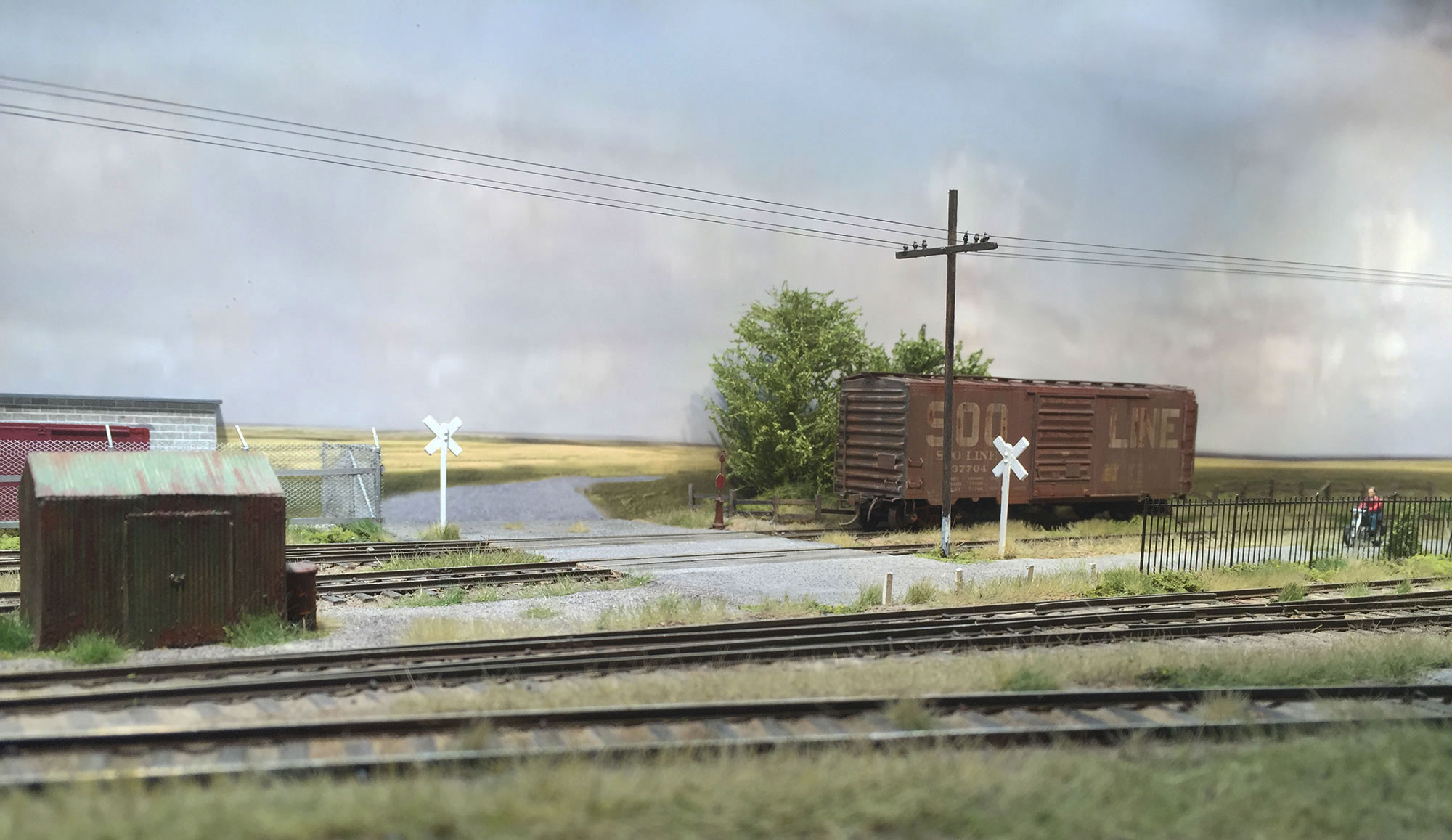
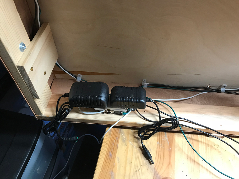
Power comes into the module using this adapter which itself connects to the mains.
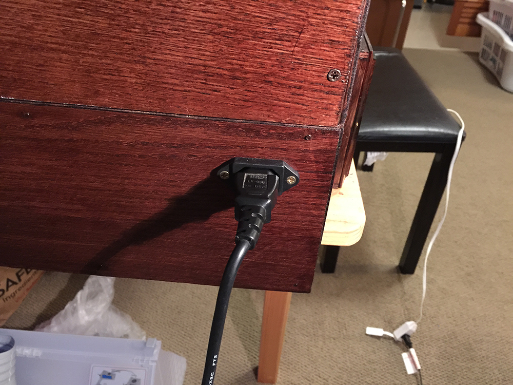
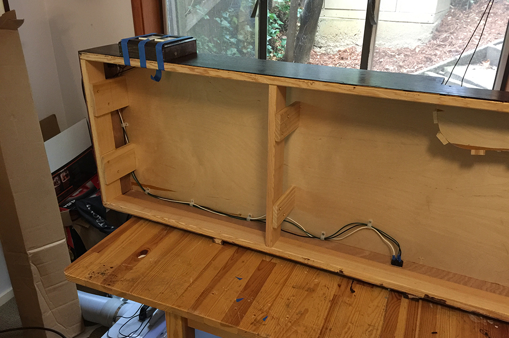
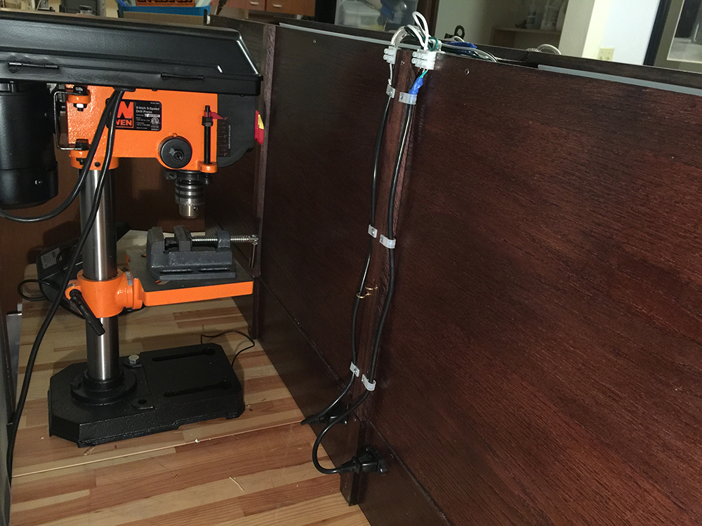
Power is run via internal wiring to the back of the module. There is also a connection to the light switches on the front.The internal wires connect to adapters into which the wires from the backdrop lights connect.There are two sets of lights: the spot lights and the fluorescent lights.I built a small box to house the switches. I have since removed this as it looked pretty ugly.
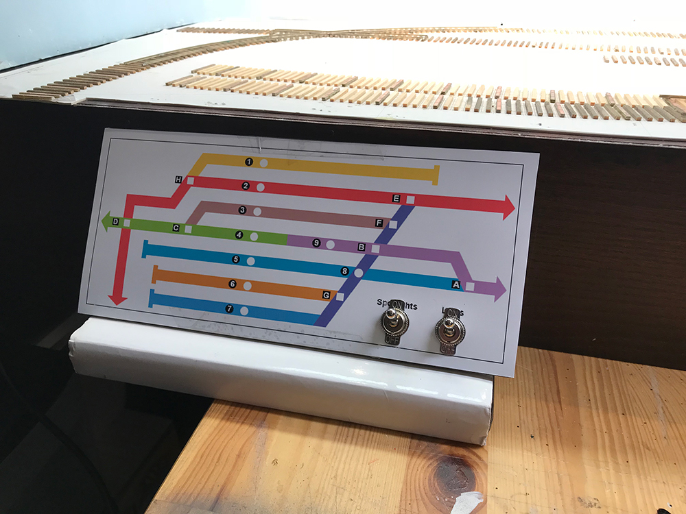
I took this basic AC system and rewired it to accommodate the control panel and two new lighting switches.
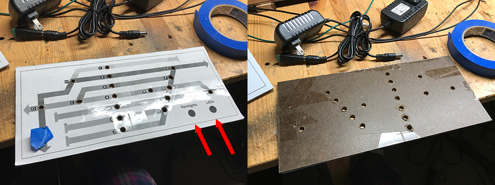
I grabbed a two-plug outlet from my box of AC components left over from various projects. The power input now connects here first before heading to the lights and light switches. I added a two plug adapter in case I wanted to run two DC systems – one for the turnouts and one for the throttle. I’m not yet sure how I am going to set up the two systems but I have the option of having two separate systems if needed.I added a couple of AC switches to my vector diagram in Photoshop and then printed out a black and white template. I used this to position the drill for the switch openings. I added two larger holes for the AC toggles.I added a couple of AC toggles to the control board. They look a little clunky right now. I’ll remove the small on off indicator plates later this week. The switches can be removed from the board if necessary. In fact the diagram is going to go through several changes/improvements so everything has to be easily removed.I’m still waiting for my brackets from Shapeways but things are coming together nicely in the meantime. The lights worked as soon as I turned them on. No shorts and no issues whatsoever. Now I’m ready to tackle the DC system which is going to be alot more complicated.
Throttle
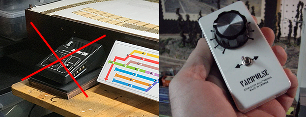
I’ve decided to get rid of my original throttle plan as I’m trying to reduce the footprint of the controller as much as possible. I found this hand-held throttle online and ordered one. I’ll just connect it via some kind of plug-in male/female adapter. It will connect to the DC system and then to the various sections. I’ll have more on that another time.
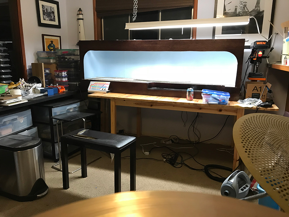
The goal is to have a simple lightweight control panel that gets the basic job done. I’m slowly getting there.