Control Panel

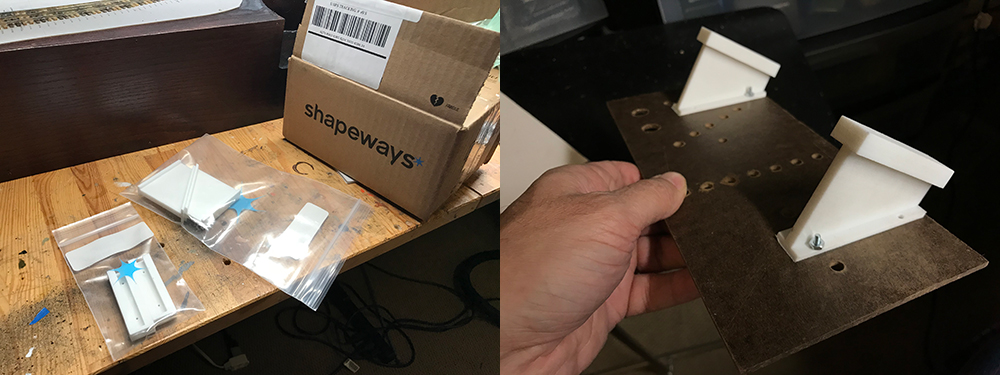
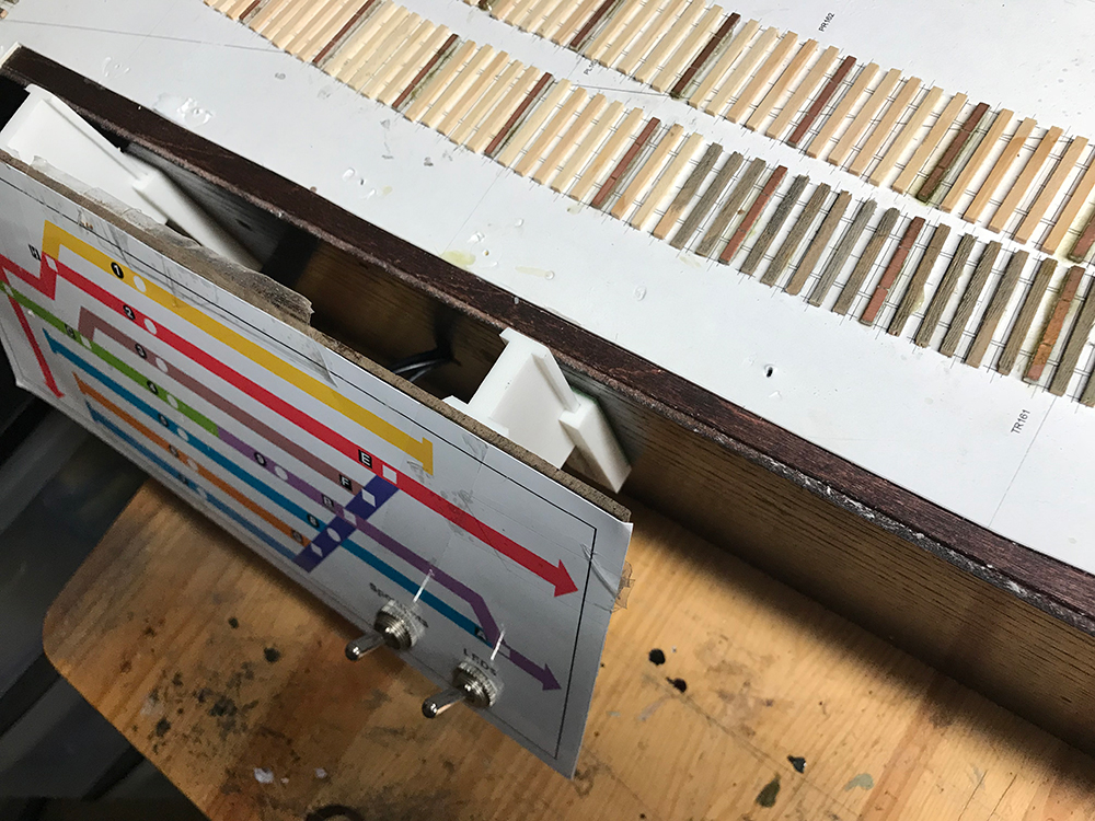
My brackets arrived from Shapeways and I waited no time to fit them. They are made of very tough plastic that called strong white and flexible. From the Shapeways site:

This material is incredibly versatile, and can be used for a wide variety of applications, from iPhone cases to jewelry, remote controlled quadcopters to wearable bikinis. When thin, it’s flexible enough for hinges and springs. When thick, it’s strong enough for structural components.

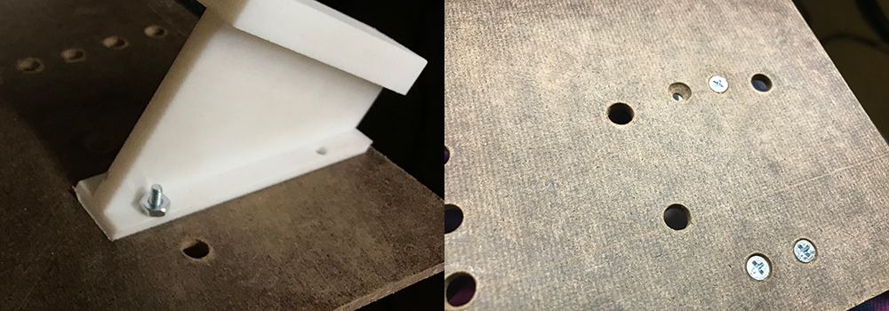
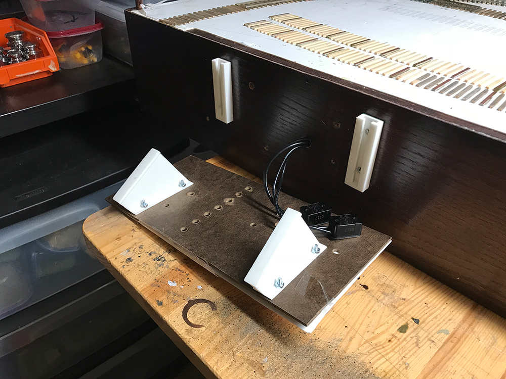
There was no doubt that the brackets were going to do a good job. My task was to sand them down so that the controller attachment slid nicely and easily into the board attachment.

I left no space between the two parts and as a result of less-than-accurate molding the brackets did not at first slide nicely. I had to spend about twenty minutes on each sanding down surfaces until they started working well together.
Eventually I was able to get them to work nicely together.
I used small nuts and bolts to attach the board brackets. This mean that if I wanted to swap out the board in the future or do more work on it then I could easily remove the brackets.
Mounting the board was straightforward enough. I had to drill counter-sinks into the board brackets to clear the screw heads but once that was done the controller brackets slide easily. The goal of the design was to give easy access to the wiring and keep the board small and lightweight.
Once the two pieces were attached the unit was very firm. I had to move the brackets to the top of the board to give clearance to the various switch holes so I didn’t quite achieve the floating look I wanted.
To remove the board all I have to do is pull up it up. It slides easily clear of the brackets.
The work-space during this part of the project. Once I had confirmed the lighting worked the backdrop cover went back to its shelf.
DC Wiring

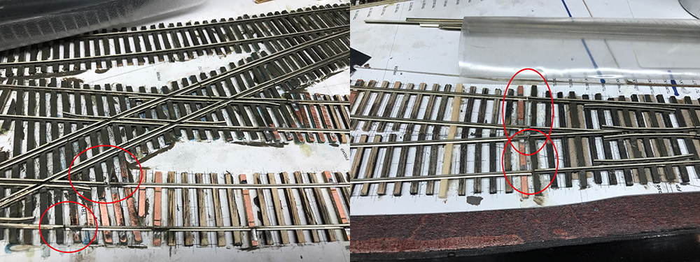
Withe controller now correctly positioned it was time to start the hard part: the DC wiring system. The key to this part of the project is simply take your time and work on one section at time without thinking too far ahead. For example if I gave any thought to the frog issues of the turnouts and the crossover I started to panic. I kept things simple and just focused on the first section.

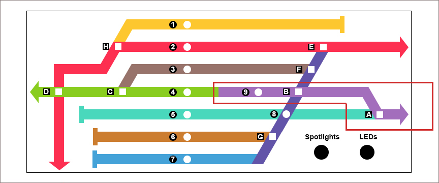
The first section is the entry-point on the right. The goal here is to:

  1. Relay the track where necessary to create distinct sections.
  2. Isolate all the rails and test for shorts.
  3. Get the straights running first and connected to SPST switches to turn power on and off.
  4. Get the turnout motors fitted, connected to theĀ  DPDT switches, get the frogs polarity switching working and test and move on.

This is the process for each of the sections. The most challenging parts will be the crossovers so once this first section is completed I will get started on those immediately after.

To get started I pulled up some of the rails that I had previously laid in order to replace them with single sections that met the crossovers closer than before. It was simple enough to remove the rail but I ruined most of the copper ties and they needed to be replaced as well.
I glued down new copper ties. Here’s a work-space shot showing the weights doing their job. The weights have proved to be once of the best tools I ever purchased.
Here’s the track in place with the new rails. Very easy and fast to install. I’ve getting better and better at soldering so I moved quickly through the track-laying part. The rails are isolated at either end.
The rails have gaps at either ends and they will be wired to a bus. Each section will have it’s own bus which will have two parts – a return wire to the general shared return bus and and a wire to the SPST switch on the controller which will turn power on and off.