
Just a quick note to those wondering where I have gone. Still here but taking a break from the hobby to deal with life events. I spent the last two and a half years working as a sub-contractor (software architect) for Visa. That contract ended last September but while I was out of the marketplace I hadn’t realized how much of my bread and butter work had been automated as well as off-shored to foreign developers. When I came out of my contract many of my previous clients had begun using automated web-building services – leaving me without work! Continue reading “Still here”
DC Wiring Part 2 – Powering the track continued
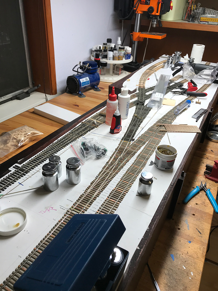
Well I finally finished the wiring to power all the track. The two separate sections (the branch line and the traction freight line) are controlled from their own SPST switches. The crossovers required a little thought and in the end I came up with a couple of schemes to wire them up. I created a third bus not connected to either of the other two sections. The crossovers will always be on and are directly connected to the throttle. In order to control the frog poles I connected them to a DPDT switch and simply flip the switch to power the correct frogs for either direction.
Continue reading “DC Wiring Part 2 – Powering the track continued”
DC Wiring Part 2 – Powering the track – the first bus
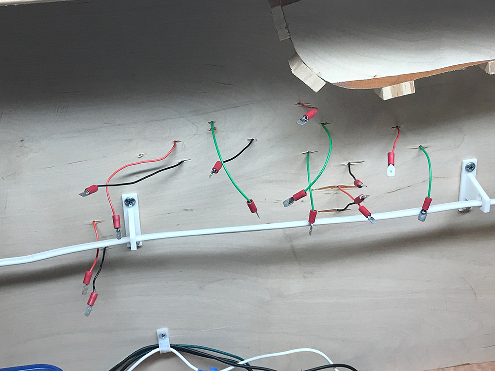
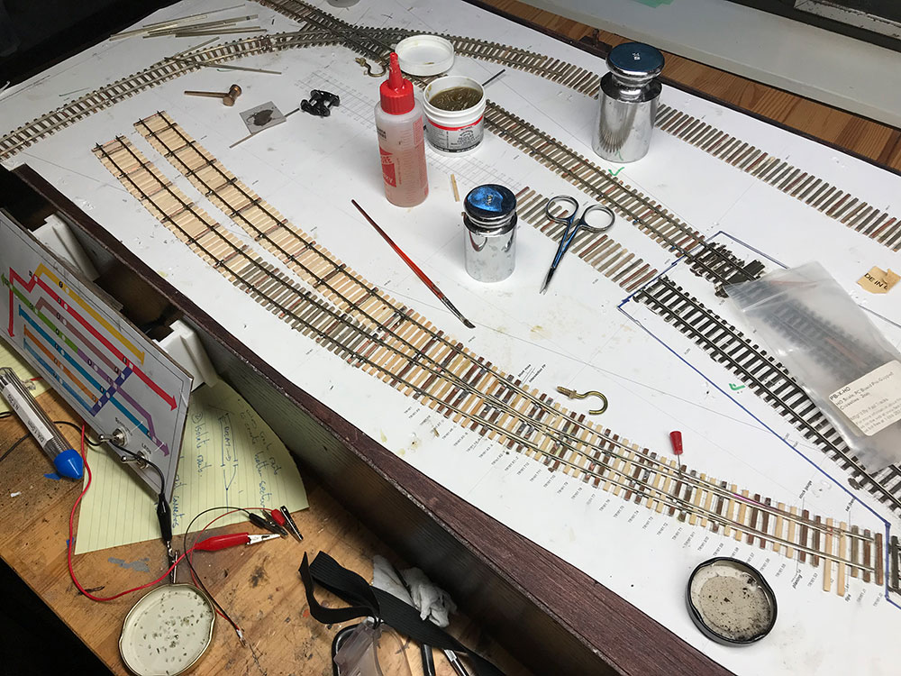
It took a couple of weeks for my bus clamps to arrive so I just carried on dropping wires through the board to eventually connect to the bus. The black is positive, the is red negative and the green (that power the two-pole frogs of the crossovers) will switch between the two poles via a DPDT switch.
Continue reading “DC Wiring Part 2 – Powering the track – the first bus”
DC Wiring Part 2 – Powering the track
Having finished isolating track the task was now to start powering the trackwork. There are going to be three independent DC systems:
- Powering the sections.
- Powering the turnouts.
- Powering any lights and accessories around the layout.
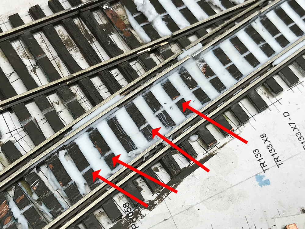
Before starting wiring I decided to clean up some of the track. I polished down many of the solder joints but importantly I filled in the gaps in the PCB ties and the gaps in the rails in the crossovers.
DC Wiring Part 1 – Lay track and isolate sections – Crossovers
Back to the project afer a short break. I continued to lay missing sections which I then isolated followed by the turnouts and finally the crossovers.
Continue reading “DC Wiring Part 1 – Lay track and isolate sections – Crossovers”
DC Wiring Part 1 – Lay track and isolate sections
Now that the control panel has been designed and fitted I have begun the wiring. The steps are basically:
- Lay missing sections of track.
- Isolate rails .
- Connect sections to the control panel.
- Wire up the crossovers and connect them to the control panel.
- Add the turnout motors and connect them to the control panel.
- Add three docks to the exit points for the removable cassettes.
Continue reading “DC Wiring Part 1 – Lay track and isolate sections”
Control Panel
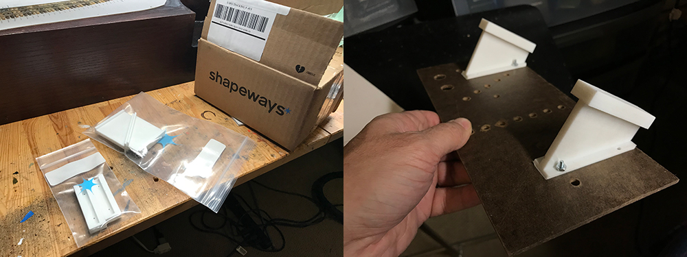
My brackets arrived from Shapeways and I waited no time to fit them. They are made of very tough plastic that called strong white and flexible. From the Shapeways site:
This material is incredibly versatile, and can be used for a wide variety of applications, from iPhone cases to jewelry, remote controlled quadcopters to wearable bikinis. When thin, it’s flexible enough for hinges and springs. When thick, it’s strong enough for structural components.
There was no doubt that the brackets were going to do a good job. My task was to sand them down so that the controller attachment slid nicely and easily into the board attachment.
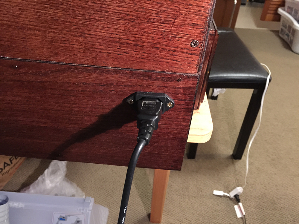
AC system
I managed to set up the internal AC electrical system which provides power to the DC adapter/s and the lighting system. I built the lighting system a while ago but had housed the switches in an ugly box that protruded from the front. I removed this and have now located the switches on the control panel.
I’ve covered the lighting system in the past but as a quick reminder here are some pics of the process:
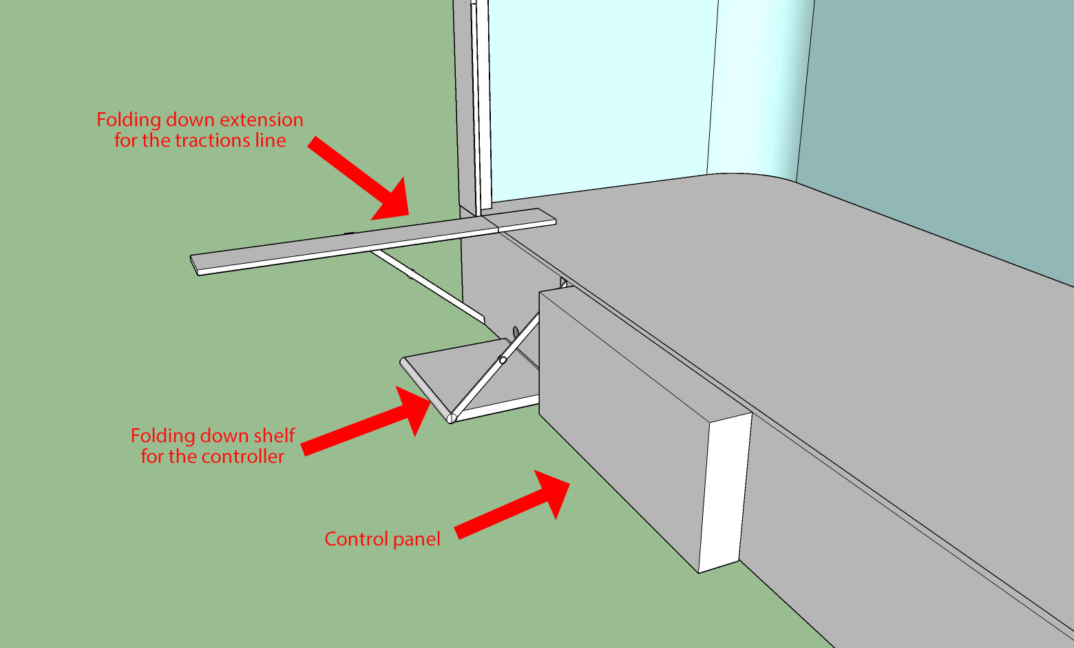
Control panel designs
So I’ve started working on the control panel design. The work has to be divided up between different functions required. Firstly laying out the space available for the controller, control panel and traction extension (see diagram). Then I need to select and design the hardware solutions and then finally decide on the panel front design. Tonight I attempted to layout the space roughly and get an idea of how to install the hardware pieces to hold the whole thing together.